
Image display apparatus

a technology of image display and display screen, which is applied in the direction of picture reproducers using projection devices, television systems, instruments, etc., can solve the problems of insufficient effect of visual mute or a/v mute, inability to completely black out the image on the display screen, and inability to restore the display quickly, so as to achieve the effect of reducing the output luminance of the lamp and the undesired sound of the fan, and restoring the normal display quickly

Inactive Publication Date: 2009-03-05
SEIKO EPSON CORP
View PDF6 Cites 6 Cited by
  • Summary
  • Abstract
  • Description
  • Claims
  • Application Information

AI Technical Summary

Benefits of technology

The invention is an image display apparatus that can adjust the output of its lamp and fan when in a visual mute mode or an A / V mute mode. This allows for a more effective mute mode by reducing the impact of the lamp and fan on the display screen. The apparatus also includes a speaker for outputting sound and an audio adjusting means for controlling the output of the speaker. This allows for appropriate audio adjustments when in the mute mode. The construction of the invention is particularly useful for projectors that use an extra-high pressure mercury lamp as a light source.

Problems solved by technology

Therefore, when a blackened image is displayed on the display screen of the image display element, illumination light is transmitted through the display screen and thus the image on the display screen cannot be made completely black.
Further, since the cooling fan keeps operating, undesired sound of the fan stands out, and thus the effect of the visual mute or the A / V mute is not achieved sufficiently.
On the other hand, if the illumination lamp is turned OFF when setting the visual mute mode or the A / V mute mode, it takes too long to restore the display in the case of canceling the setting of the mode.
Therefore, electrons can hardly move from cathode to anode even when high voltage at a high frequency is applied in such state, so that discharge cannot be started soon in the tube.
As a consequence, it is impossible to relight the lamp immediately.
Therefore, switching the mode of the display screen between a display mode and the visual mute mode as desired by turning the lamp ON and OFF requires a long waiting time, and hence is inappropriate in terms of users' environments.

Method used


Image

  • Image display apparatus
  • Image display apparatus
  • Image display apparatus

Examples


first embodiment

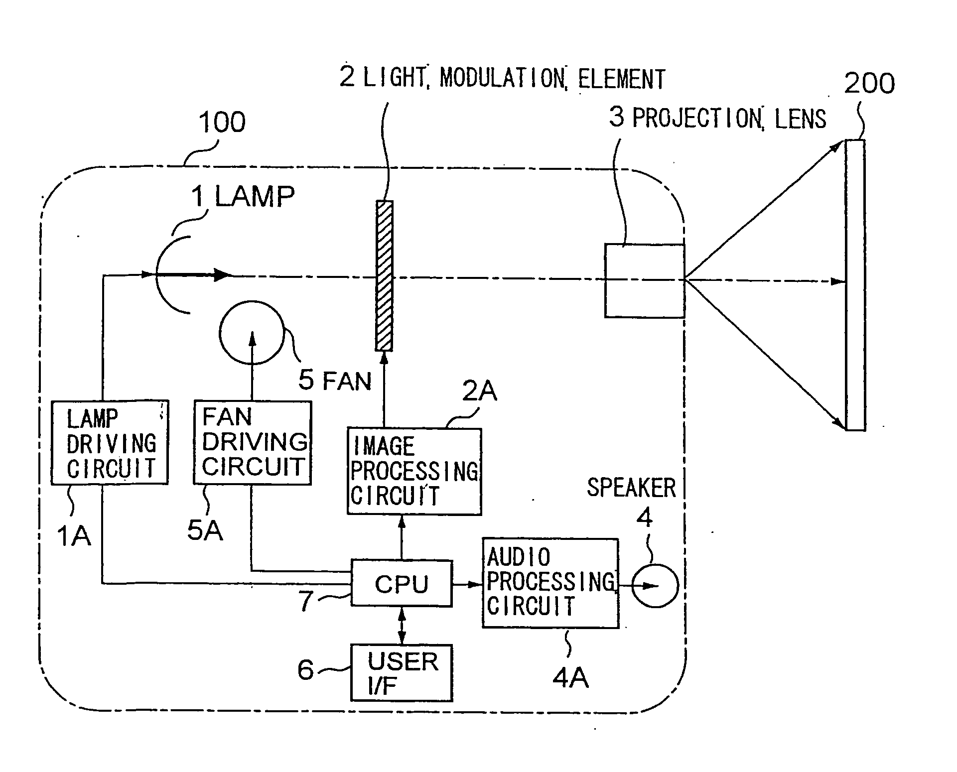
[0023]FIG. 1 is a block diagram showing a principal construction of a single panel projector for describing an embodiment of the invention. An projector 100 includes, as shown in the figure, a lamp 1 as an illumination light source, a light modulation element 2 such as a liquid crystal panel being illuminated by the lamp 1 and displaying images based on predetermined image information, and a projection lens 3 for projecting the images generated by the light modulation element 2. The projector 100 also includes a lamp driving circuit 1A for driving the lamp 1, an image processing circuit 2A for supplying image information to the light modulation element 2, a speaker 4 for outputting sound, an audio processing circuit 4A for supplying audio information to the speaker 4, a fan 5 for cooling the lamp 1 and / or the light modulation element 2, a fan driving circuit 5A for driving the fan 5, a user interface 6 including an input device for supplying various control information and data to t...

second embodiment

[0048]FIG. 4 is a block diagram showing a principle construction of a three-panel projector for describing the second embodiment of the invention. A projector 300 separates illumination light from a lamp unit 13 into red light (R), green light (G), and blue light (B) using a colored light separating optical system 8, projects the separated colored lights on liquid crystal panels 2R, 2G and 2B, which are light modulation elements provided for the respective RGB signals of an image, to display images thereon, combines the respective colored images by a cross dichroic prism 9, and projects a combined image through the projection lens 3. In FIG. 4, the same reference numerals as FIG. 1 show identical or corresponding components in FIG. 1.

(i) Construction Relating to the A / V Mute Function

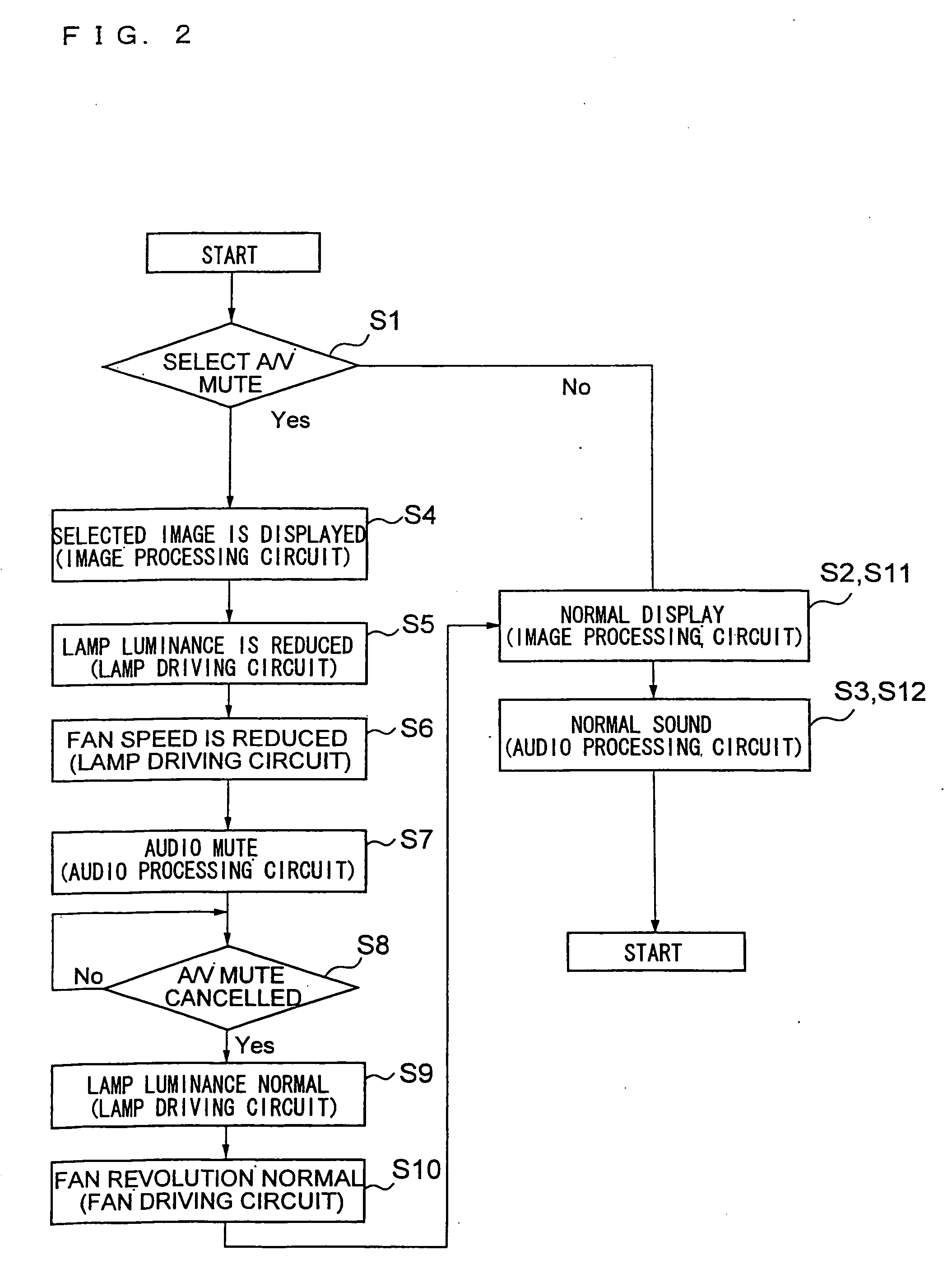
[0049]In this three-panel projector 300, when the A / V mute mode is set, signals of no image or a predetermined image are sent to the respective liquid crystal panels 2R, 2G, 2B from the image processing ...


PUM

PropertyMeasurementUnit
temperatureaaaaaaaaaa
luminanceaaaaaaaaaa
luminance intensityaaaaaaaaaa

Abstract

A projector (image display apparatus) having enhanced visual mute or A / V mute functions includes a light modulation element for displaying an image, a lamp for illuminating the light modulation element, and a fan for cooling the lamp; the image display apparatus further includes a visual mute means for setting a visual mute mode in which no image or a predetermined image is displayed on a display screen thereof, and a lamp output luminance adjusting means for adjusting the output luminance of the lamp in response to the setting and canceling of the visual mute mode by the visual mute means.

Description

[0001]This is a Continuation of application Ser. No. 10 / 379,576 filed Mar. 6, 2003. The disclosure of the prior application is hereby incorporated by reference herein in its entirety.BACKGROUND OF THE INVENTION[0002]1. Field of the Invention[0003]The present invention relates to an image display apparatus, and, more specifically, to a projector including an image display element, a lamp for illuminating the image display element, and a fan for cooling the lamp. The invention also relates to a technique for setting a mode in which no image or a predetermined image is displayed on a display screen of the image display apparatus, without stopping the action of the lamp, and to a technique for canceling such setting.[0004]2. Description of the Related Art[0005]Generally, in a projector of the related art, when the user selects a mode to display no image, or a predetermined image on a display screen (hereinafter referred to as “Visual Mute Mode”), keeping a main power supply in the ON-st...

Claims


Application Information

Patent Timeline
Patent Type & Authority Applications(United States)
IPC IPC(8): G09G5/00G03B21/00G02F1/13G03B21/16H04N5/74H04N9/31
CPCH04N5/74H04N9/3197H04N9/315H04N9/3144
Inventor NAITO, KEIJIRO
Owner SEIKO EPSON CORP
Learn More