
Plant biomass solid fuel

a solid fuel and plant biomass technology, applied in the direction of biofuels, solid fuels, shaping presses, etc., can solve the problems of increasing cost, less than entirely suitable as fuel, and relatively expensive briquettes, and achieve high quality solid fuel, and enhanced cube durability and energy content

Inactive Publication Date: 2009-03-05
GAUTHIER STEPHANE +4
View PDF9 Cites 52 Cited by
  • Summary
  • Abstract
  • Description
  • Claims
  • Application Information

AI Technical Summary

Benefits of technology

The present invention provides a solid fuel material made from plant biomass materials that can be used in various heating systems. The fuel is made from a mixture of agricultural crop residues and paper products that are blended together to create a high-quality solid fuel. The invention involves cubing the biomass material and then densifying it in a cubing device before cooling it. The resulting fuel has enhanced durability and energy content, with the cellulose and lignin content of the material forming a briquette that binds the particles together. The invention also involves using a modified cubing system that uses a combination of agricultural crop residues and paper products to create a high-quality solid fuel.

Problems solved by technology

Coal is widely available but is increasing in cost and also contains many contaminants which render it less than entirely suitable as a fuel.
However such briquettes are relatively expensive and do not provide the characteristics of coal as a fuel.
Yet further the briquettes are expensive to produce since the materials from which they are produced must be dried and the briquettes tend to produce significant quantities of fines or dust when broken down.
These characteristics reduce the desirability of such briquettes as a replacement for conventional coal in residential or commercial furnaces.
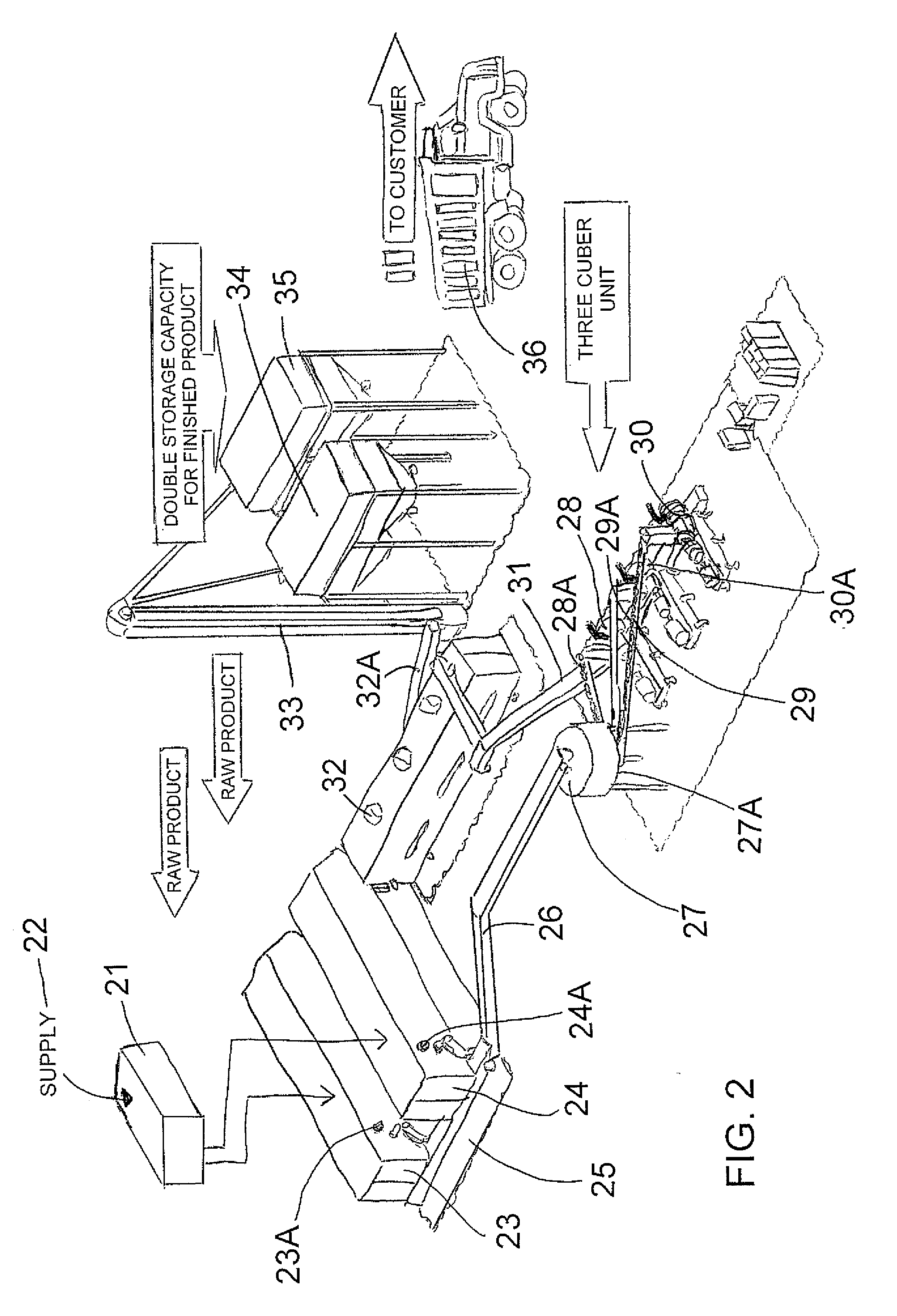
Some attention has been given to the possibility for using such Cubers for compressing other materials but little or no success has been achieved to date.

Method used


Image

  • Plant biomass solid fuel
  • Plant biomass solid fuel
  • Plant biomass solid fuel

Examples


Embodiment Construction

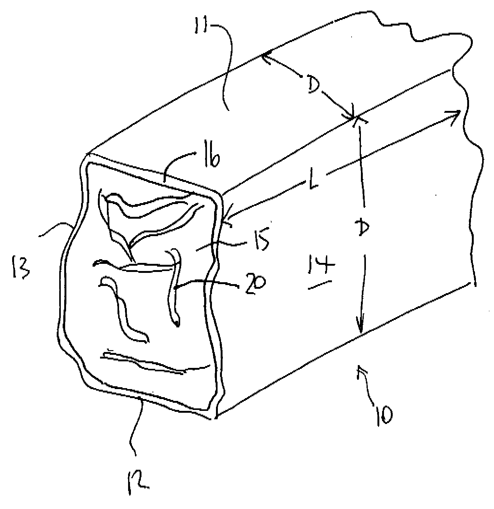
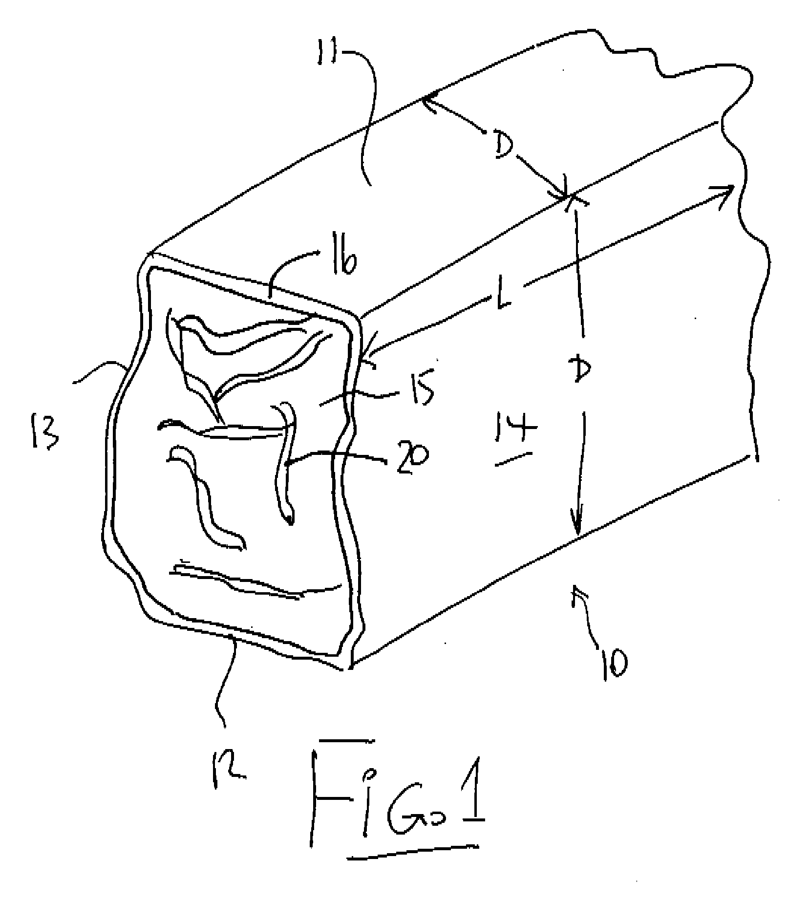
[0091]In FIG. 1 is shown one piece formed by the cubing system described herein after. This single piece is indicated at 10 and forms one of a multitude of such pieces which are extruded and then broken to length as described herein after.

[0092]Each piece 10 is extruded in square cross section to form top and bottom surfaces 11 and 12 and side surfaces 13 and 14. These surfaces are flat and are formed from the inside surface of the die as described herein after.

[0093]The piece so formed is formed from the plant biomass material previously described where the high temperatures generated in the compression process of the Cuber acts to cause the cellulose in the material to act as a binder within a central area 15 of the piece. Lignin within the material is driven to the exterior and is polymerized by the high temperature action to form a hard outer casing 16.

[0094]The high compression of the cubing system described herein after provides a densification of the materials to provide a de...


PUM

PropertyMeasurementUnit
lengthaaaaaaaaaa
widthaaaaaaaaaa
lengthaaaaaaaaaa

Abstract

A solid fuel is formed in a cuber to form body pieces formed of materials extruded through a die with a density greater than 35 lbs / cu ft; an energy content greater than 6500 BTU / lb; transverse dimensions less than 1.5 inches; and a length less than 4 inches; from plant biomass material which contains components when extended of greater than 1.0 inch. Primarily the materials are paper or other cellulose product and crop residue such as wheat straw. The cellulose and lignin from these materials act without additional binders as binders and encasing materials. The moisture content is maintained at a target value by mixing selected quantities of the materials without drying. The cubing machine has a feeding system where the space between the inner rotor and outer casing is smaller than 4 inches and the height of the outer flight is less than 1 inch.

Description

[0001]The invention is related generally to the field of plant biomass solid fuel.[0002]This application relates to and contains common subject matter with two co-pending applications filed on the same date by the same applicants under Attorney Docket Nos. 85776-102 and 85776-202.BACKGROUND OF THE INVENTION[0003]Enormous quantities of agricultural residues or plant biomass materials are produced as by-products of agricultural and commercial processing. Some of these products include Flax Shives which are currently being used for bedding and for heating in large stoker boilers. Other agricultural crop residues found in large quantities include; Wheat Straw, Barley Straw, Corn Stover, Kentucky Blue Grass Screenings, Switch grass and Bagasse. All of these can be collected and cubed to produce solid fuel.[0004]The other product involved in this invention is paper residues collected from recycling facilities. Due to the decrease in demand for recycled paper products, more of these produc...

Claims


Application Information

Patent Timeline
Patent Type & Authority Applications(United States)
IPC IPC(8): C10L5/44
CPCB30B11/201B30B11/207Y02E50/30C10L5/44Y02E50/10C10L5/361
Inventor GAUTHIER, STEPHANEGALA, EUGENEBALCEAN, ROGERBROESKY, SHAUGHNNADEAU, PIERRE
Owner GAUTHIER STEPHANE
Learn More