
Home Care Equipment Monitoring System

Inactive Publication Date: 2009-02-26
PARAMOUNT BED CO LTD +1
View PDF5 Cites 13 Cited by
  • Summary
  • Abstract
  • Description
  • Claims
  • Application Information

AI Technical Summary

Benefits of technology

[0025]The home care equipment monitoring system according to the present invention includes a home care equipment whose at least one drive unit can be actuated by an electric drive means based on the operation by the user, a sensor means for detecting the actuation state of the drive unit, a first control means for figuring out the actuation state of the drive unit based on a detection signal output from the sensor means, and storing the performance history of the drive unit in a storage means as operation history information, and a second control means for displaying the operation history information on a display means in a predetermined pattern. Accordingly, the operation history information of the home care equipment can be displayed on the display means, and, by taking a look at the display means, a care personnel, a care manager, etc. can easily figure out the operation history situation of the user of the home care equipment, and can recognize the detailed living situation correctly. Furthermore, it becomes possible to easily check whether or not the user or a person requiring nursing care, patient, inmate of care facility etc. properly uses the home care equipment. Accordingly, proper advices are given and proper care plans are formed for respective users of the home care equipment, and the care plans can be continuously modified according to the physical condition and state of use, which can maintain and improve the quality of living of the respective users.
[0026]For example, since the means to transmit the operation history information to the second control means is arranged, it becomes possible for a care manager etc. at a remote place to easily figure out the state of use of the home care equipment. Accordingly, by giving an advice about the proper manner of using the home care equipment from a remote place, and checking the state of use of the home care equipment in advance before visiting the user of the equipment, the efficiency in giving an advice and a guidance at the time of visiting the user can be improved. Furthermore, since the transmission means is mounted to the home care equipment, the second control means can transmit the operation history information to the outside of the home care equipment, which makes it possible to transmit the operation history information to a server etc. arranged at a remote place through wired or wireless means. In this case, when arranging a server in a nursing and personal care facility, managing the state of use of the home care equipment and the health care can be carried out at the same time for inmates of the facility.

Problems solved by technology

So, it is difficult for a care manager etc. to figure out daily living situations of the respective persons in detail all the time.
Furthermore, time periods to be spent for the hearings are limited, which also makes it difficult to completely figure out the daily living situations, and inevitably raises insufficient recognitions.
On the other hand, in case family members of a person to be cared for live far away from the person, the person cannot be cared for sufficiently.
In case family members of a person to be cared for live far away from the person, it is difficult for even the family members to figure out the daily living situation of the person in detail, and, when an abnormal circumstance happens to the person, the family members cannot respond to the abnormal circumstance immediately.
However, as described above, since the care personnel is busy, and the family members have to do works and child-rearing tasks, it is a big burden to visit the person frequently.

Method used


Image

  • Home Care Equipment Monitoring System
  • Home Care Equipment Monitoring System
  • Home Care Equipment Monitoring System

Examples


first embodiment

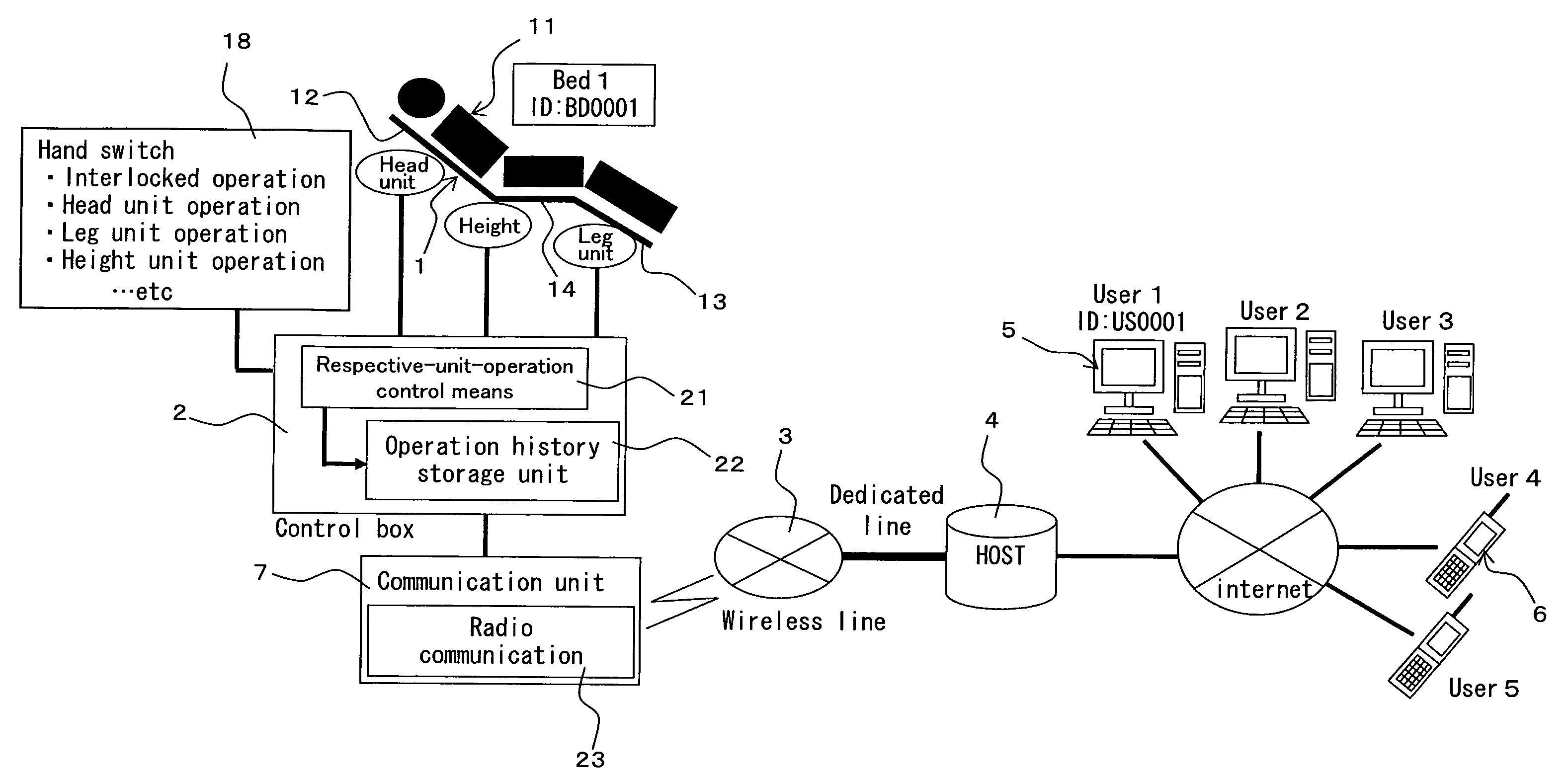
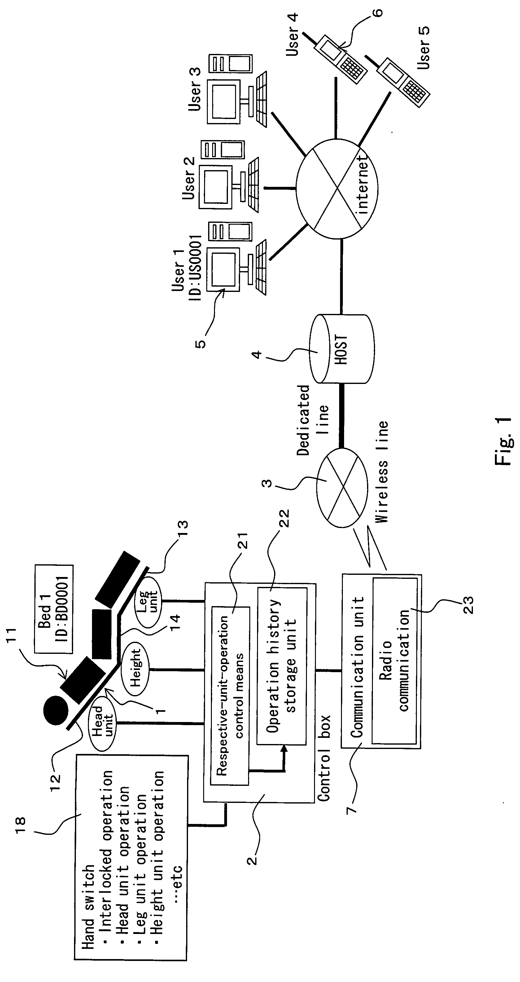
[0083]FIG. 1 shows an explanatory diagram indicative of the entire configuration of a home care equipment monitoring system according to a first embodiment of the present invention. In the system, as shown in FIG. 1, operation history information of an electric bed (home care equipment) 1 is stored in a control box (first control means) 2, and the operation history information is transmitted to a host computer (second control means) 4 through a wireless line (communication line) 3. The host computer 4 can be accessed from personal computers 5 (hereinafter, referred to as computers 5) or cellular phones 6 of the respective users through the Internet line, and, according to the request of the users, the operation history information is provided from the host computer 4 to the computers 5 and the like.

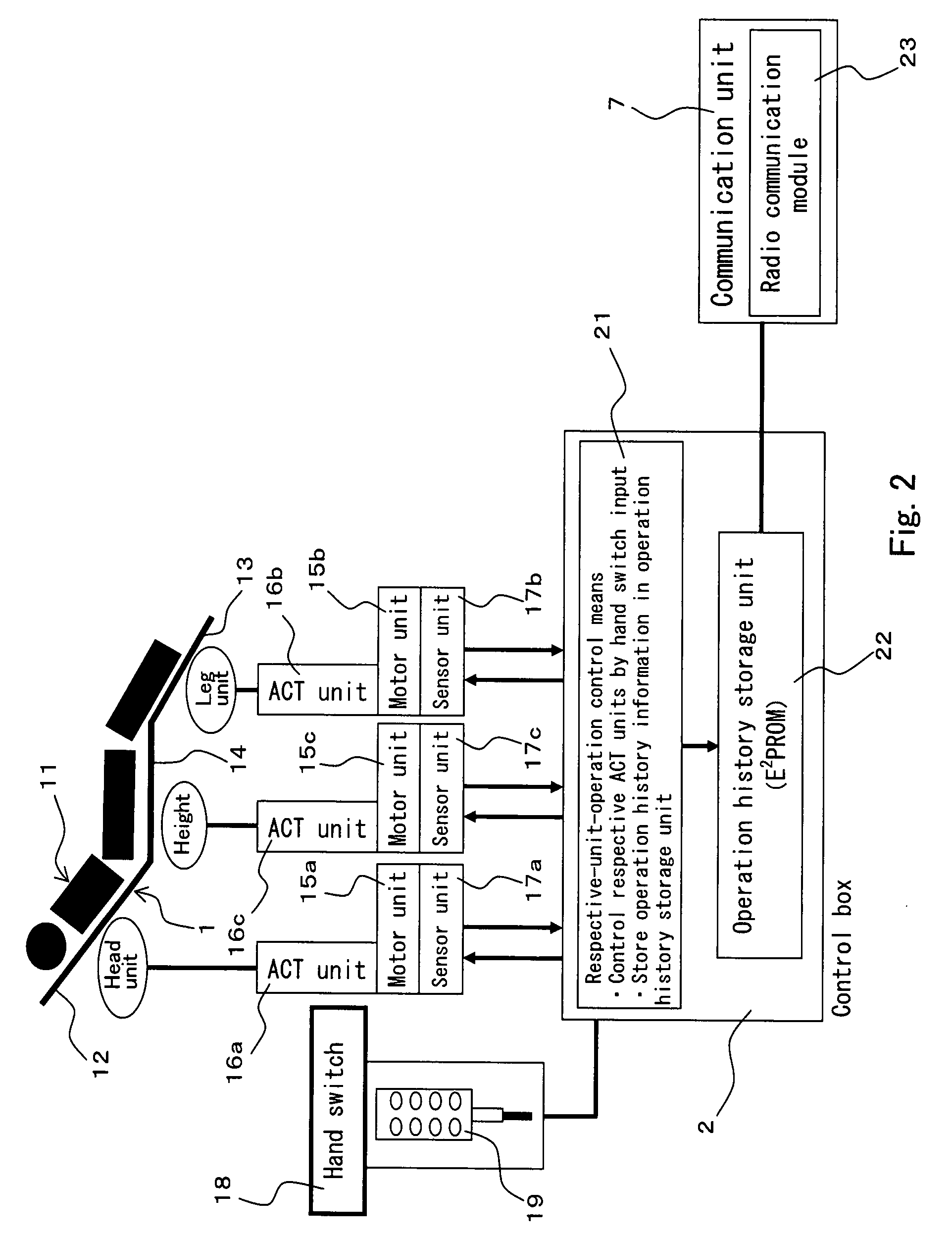
[0084]FIG. 2 shows a block diagram indicative of the system configuration of the electric bed 1 (hereinafter, referred to as bed 1) side. The bed 1 is used by a person to be cared for 11 ...

second embodiment

[0113]Next, as a second embodiment of the present invention, a home care equipment monitoring system employing an electric wheelchair will be explained. FIG. 11 shows a block diagram indicative of the system configuration of the electric wheelchair side. In this embodiment, parts or components similar to those of the first embodiment are indicated with the same reference numerals, and detailed explanation of which will be omitted. In the system, similar to the system shown in FIG. 1, operation history information of an electric wheelchair (home care equipment, hereinafter referred to as wheelchair) 41 is stored in a control box 42, and the operation history information is transmitted to the host computer 4 through the wireless line 3.

[0114]The wheelchair 41 has right and left drive wheels (drive unit) 43a, 43b. At the drive wheels 43a, 43b, motor units (electric drive means) 44a, 44b using electric motors are arranged. To the motor units 44a, 44b, sensor units 45a, 45b (sensor means...


PUM


Abstract

In a bed (home care equipment) 1, based on the switch operation, respective drive units of a head unit 12, a leg unit 13, and a height adjustment unit 14 are actuated by motor units 15a to 15c and actuator units 16a to 16c. The actuation state of the respective drive units are detected by the sensor units 17a to 17c, and a respective-unit-operation control means 21 figures out the actuation state of the drive units based on a detection signal, and stores the performance history of the drive units in the operation history storage unit 22 as operation history information. The operation history information in the operation history storage unit 22 is transmitted to a host computer 4 by a communication unit 7. The host computer 4 processes the received operation history information to data which can be displayed by the animation display, graph display, and accumulated time period display, and transmits thus processed data to a computer 5 etc. which is connected to the host computer 4 through the Internet line.

Description

TECHNICAL FIELD[0001]The present invention relates to a home care equipment monitoring system that figures out living information of a person who requires nursing care or a person who requires support so as to establish the most suitable living environment for such a person requiring nursing care etc., and more particularly, to a home care equipment monitoring system that obtains the living information of a person requiring nursing care etc. based on the state of use of an electric bed or an electric wheelchair.BACKGROUND ART[0002]In late years, along with the establishment of the nursing care insurance system, for persons who have to be cared for and need nursing care or support in leading a usual life such as old people, physically handicapped persons, incurable disease sufferers (persons who require nursing care or persons who require support), respective care plans best suited to the respective persons to be cared for are created by qualified care managers. In forming a care pla...

Claims


Application Information

Patent Timeline
IPC IPC(8): G06Q50/00A61G7/05A61G5/04G07C3/00A61B5/00A61G7/00A61G12/00G16H40/63G16H40/67H04Q9/00
CPCA61G5/04A61G5/10G06Q50/22A61G2203/14G06F19/3418A61G7/018G16H40/67G16H40/63
Inventor INABA, MITSUNORIKAWAGOE, KUNIAKINAGASE, YUICHINAGAOKA, HIROSHISHIMOKAWA, MASATOMATSUMIYA, RIKA
Owner PARAMOUNT BED CO LTD
Learn More