
Laser light source device and image generating device using same

a technology of laser light source and image generating device, which is applied in the direction of laser details, instruments, electrical apparatus, etc., can solve the problems of increasing the number of parts correspondingly, and increasing the number of parts, so as to suppress the output of the converted wave, and suppress the above-described parasitic oscillation

Inactive Publication Date: 2009-02-26
SONY CORP
View PDF2 Cites 1 Cited by
  • Summary
  • Abstract
  • Description
  • Claims
  • Application Information

AI Technical Summary

Benefits of technology

The present invention provides a laser light source device and an image generating device that can output a converted wave in a transverse multi-mode pattern while suppressing parasitic oscillation of the fundamental wave and variations in output of the converted wave. This is achieved by disposing a reflecting part for folding back a resonant light path and a polarizing film on an end surface of one of the laser medium and the wavelength converting element. The use of a separate Brewster plate or other optical element for polarization of light is unnecessary, thus reducing the number of parts and simplifying optical adjustment work. The laser light source device is also smaller and more compact than previous configurations.

Problems solved by technology

However, the following problems arise when working is provided so as to have a Brewster angle at an end surface of a crystal as in a method disclosed in the above Patent Document 2.
In this case, however, an increase in the number of parts is inevitable.
Further, even in this case, when a resonant light path is folded by using a concave mirror, the pumping direction and the direction of the harmonic may not be made parallel to each other because of a finite effective diameter of an optical system.
Therefore device configuration becomes complex.
An increase in the number of parts correspondingly complicates optical adjustment work, and affects optical characteristics, cost, and the like.
In particular, when a linear beam is folded back by a concave mirror in particular, the occurrence of aberration becomes a problem.
In addition, depending on the size of a beam, there arises a need to increase the effective diameter of the folding-back mirror, which is disadvantageous for miniaturization.

Method used


Image

  • Laser light source device and image generating device using same
  • Laser light source device and image generating device using same
  • Laser light source device and image generating device using same

Examples


Embodiment Construction

[0028]An example of the best mode for carrying out the present invention will hereinafter be described. However, the embodiment of the present invention is not limited to the example below.

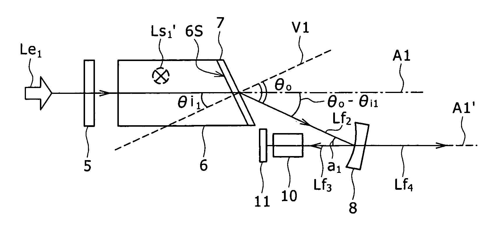
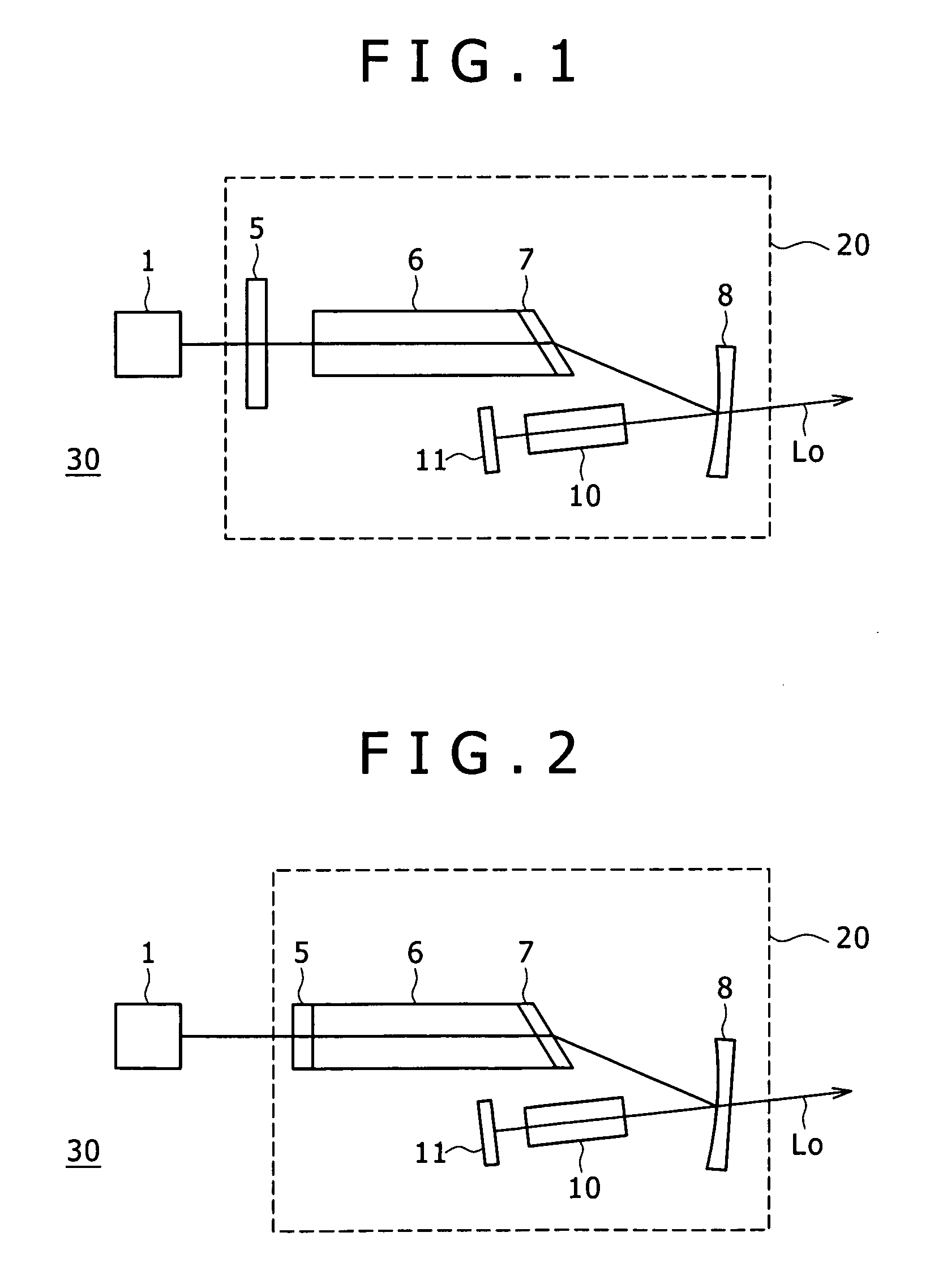
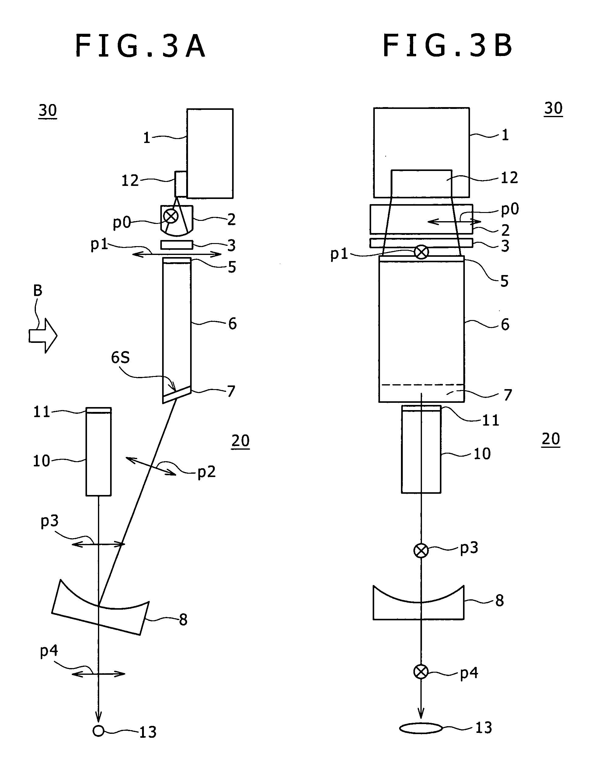
[0029]FIG. 1 and FIG. 2 are schematic diagrams of configuration of respective examples of a laser light source device according to an embodiment of the present invention. The laser light source device 30 shown in FIG. 1 has a pumping light source 1 and a pair of resonator mirrors 5 and 11. The laser light source device 30 also has a laser medium 6 and a wavelength converting element 10 within a resonator 20 (indicated by a broken line) formed by the resonator mirrors 5 and 11. The laser medium 6 is pumped by light in a transverse multi-mode pattern which light is emitted from the pumping light source 1 of a semiconductor laser array or the like. The wavelength converting element 10 is irradiated with a linear fundamental wave obtained by the oscillation of the laser medium 6, and then outputs a li...


PUM


Abstract

Disclosed herein is a laser light source device including a pumping light source; a pair of resonator mirrors; a laser medium and a wavelength converting element within a resonator formed by the resonator mirrors; the laser medium being pumped by light in a transverse multi-mode pattern, the wavelength converting element being irradiated with a linear fundamental wave obtained by oscillation of the laser medium, and a linear converted wave being output; a reflecting part for folding back a resonant light path, the reflecting part being disposed on the light path between the laser medium and the wavelength converting element; an end surface of one of the laser medium and the wavelength converting element being formed as an inclined surface at other than a Brewster angle; and a polarizing film disposed on the inclined surface.

Description

CROSS REFERENCES TO RELATED APPLICATIONS[0001]The present invention contains subject matter related to Japanese Patent Application JP 2007-217503 filed in the Japan Patent Office on Aug. 23, 2007, the entire contents of which being incorporated herein by reference.BACKGROUND OF THE INVENTION[0002]1. Field of the Invention[0003]The present invention relates to a laser light source device that outputs linear converted light in a one-dimensional transverse multi-mode or the like as a result of internal resonator type wavelength conversion, and an image generating device using the same.[0004]2. Description of the Related Art[0005]In various optical devices using a laser light source, such as projectors, laser printers, process devices and the like, a laser light source device that has a small size, consumes low power, and provides stable output is desired. In particular, in a laser light source device that has a resonator structure using a wavelength converting element such as a nonline...

Claims


Application Information

Patent Timeline
Patent Type & Authority Applications(United States)
IPC IPC(8): H01S3/10H01S3/081
CPCG02B26/105H01S3/0621H01S3/0815H01S3/09415H01S3/1671H01S3/1625H01S3/1636H01S3/1653H01S3/108
Inventor KIMURA, KAORUOKA, MICHIO
Owner SONY CORP
Learn More