Method and apparatus for stabilizing voltage of intermediate circut of frequency converter
- Summary
- Abstract
- Description
- Claims
- Application Information
AI Technical Summary
Benefits of technology
Problems solved by technology
Method used
Image
Examples
Embodiment Construction
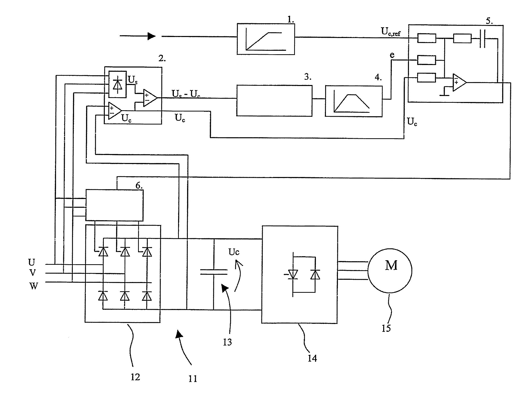
[0013]FIG. 1 schematically shows a frequency converter 11, and a block diagram implementing a method according to the invention. The figure shows main circuit parts of the frequency converter, i.e. a rectifier bridge 12, a DC voltage intermediate circuit 13, and an inverter 14. The rectifier bridge is formed as a half controlled rectifier, i.e. the upper branches of each phase are formed from controllable components which, in the solution shown in FIG. 1, are thyristors. The frequency converter 11 is connected to a supply network U, V, W and to a controllable motor 15.
[0014]FIG. 1 further shows a gate driver 6 for controlling the thyristors of the rectifier bridge. The figure shows the gate driver being coupled to the supply network. Through this coupling the gate driver synchronizes with the network and, on the basis of phase voltages of the supply voltage, concludes which thyristor is to be controlled at a given time.
[0015]Prior to using the frequency converter, the intermediate c...
PUM
 Abstract
Description
Claims
Application Information
 - R&D
- Intellectual Property
- Life Sciences
- Materials
- Tech Scout
- Unparalleled Data Quality
- Higher Quality Content
- 60% Fewer Hallucinations
Browse by: Latest US Patents, China's latest patents, Technical Efficacy Thesaurus, Application Domain, Technology Topic, Popular Technical Reports.
© 2025 PatSnap. All rights reserved.Legal|Privacy policy|Modern Slavery Act Transparency Statement|Sitemap|About US| Contact US: help@patsnap.com


