
Method of reducing hydrocarbon emissions from a cold engine and device and engine for carrying out this method

a technology of cold engine and hydrocarbon emissions, which is applied in the direction of machines/engines, electrical control, non-mechanical valves, etc., can solve the problems of improper combustion and achieve the effects of reducing ignition advance, increasing gas turbulence in the chamber, and increasing turbulen

Inactive Publication Date: 2009-02-26
PEZHO SITROEN AUTOMOBILS SA
View PDF11 Cites 6 Cited by
  • Summary
  • Abstract
  • Description
  • Claims
  • Application Information

AI Technical Summary

Benefits of technology

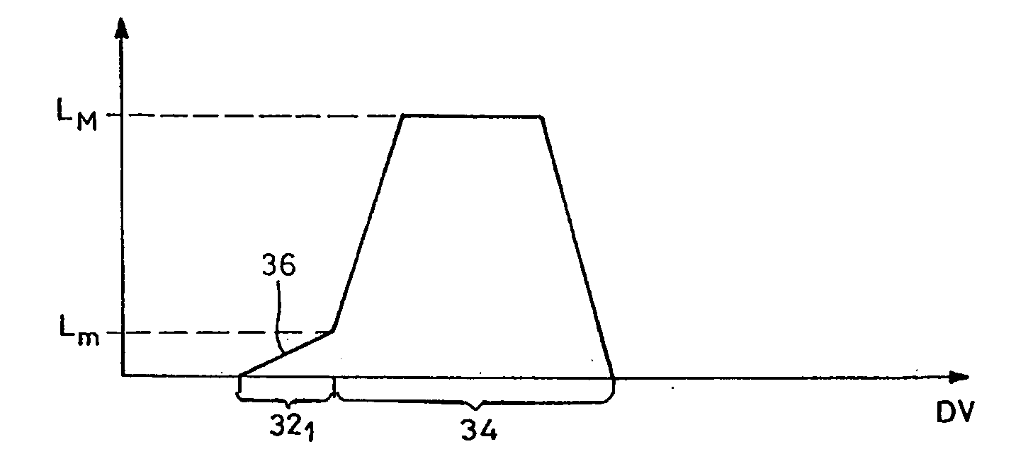
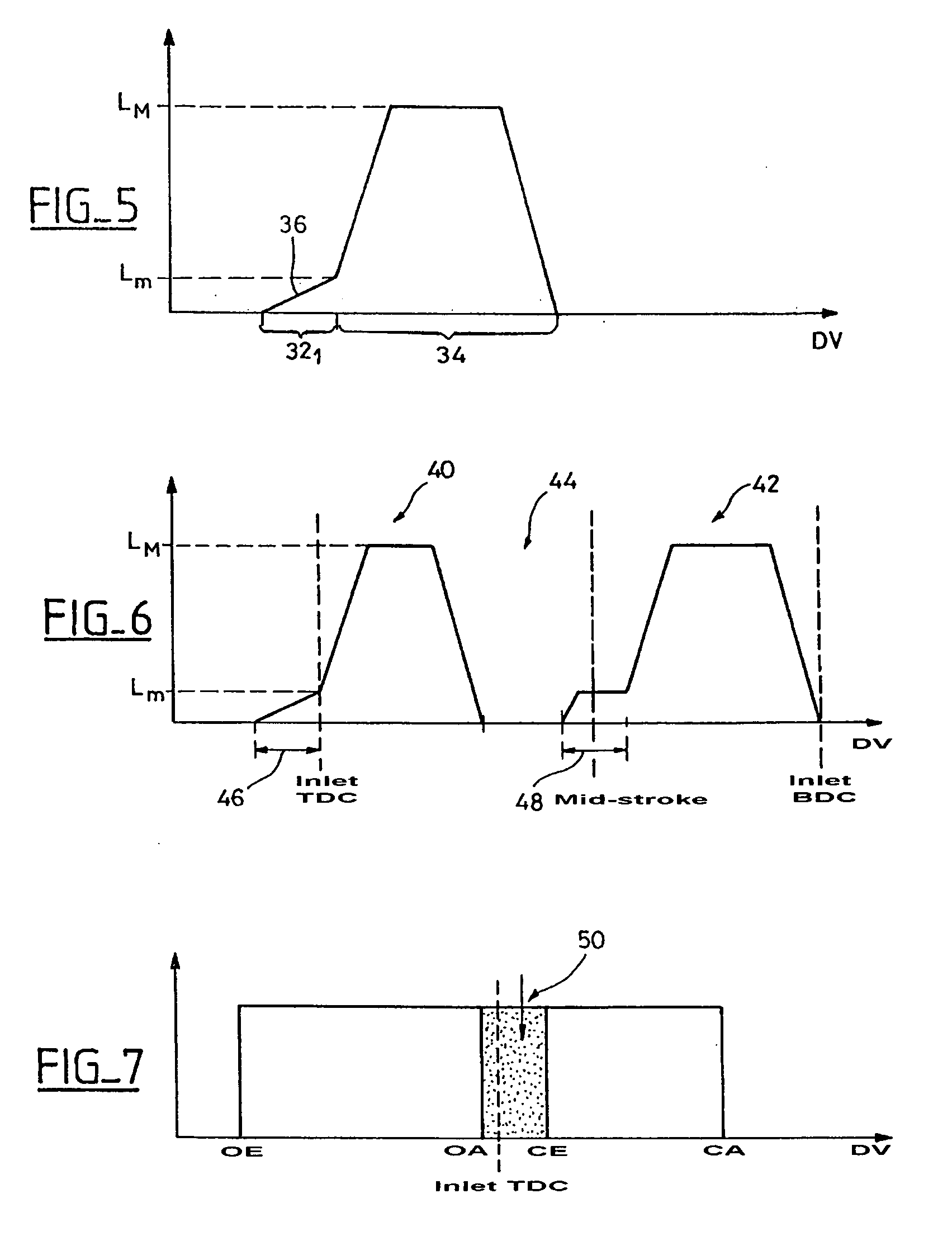
[0009]In order to properly understand the behavioural difference between the two controlling types, it is herewith noted that the fuel is injected on the valve before its opening; in consequence, in the case of a progressive opening (curve 10), the fuel is introduced into the engine cylinder while the valve lift is still low. This introduction of fuel at low lift brings about a pulverisation into fine droplets of this fuel which is introduced into the cylinder and, consequently, a better combustion.
[0013]When the valve 14 opens rapidly (FIG. 2), the large section of passage left to the fuel brings about a relatively low pulling speed by the air and therefore the formation of droplets 22 of large dimensions. Conversely, when the section of the passage is smaller, the pulling speed by the air is greater and the pulverisation much more effective, the droplets 26 introduced into the cylinder 28 being therefore of much smaller dimension than in the case of FIG. 2.
[0021]In the case of such a double lift, provision is made for an initial short lift phase, both for the pilot lift and for the main lift. The short lift at the beginning of the main lift furthermore presents the advantage of increasing the gas turbulence in the chamber.
[0027]Thus, in this embodiment, of double lift and low amplitude lift at the start of each lift, an optimal combustion and a faster activation of the catalyser(s) is obtained during the second lift (main lift). Furthermore, with the low amplitude lift at the start of the pilot lift, as indicated above, the suction back into the cylinder of part of the unburnt hydrocarbons, which are then burnt during the following cycle, is well controlled.

Problems solved by technology

The greater part of hydrocarbon emissions occur when the engine is cold, that is to say generally on start up, since, in this situation, catalysers are not activated, the quality of the air and fuel mix and the thermodynamic conditions in the cylinder are not optimised and, thereby, combustion is not properly carried out.

Method used


Image

  • Method of reducing hydrocarbon emissions from a cold engine and device and engine for carrying out this method
  • Method of reducing hydrocarbon emissions from a cold engine and device and engine for carrying out this method
  • Method of reducing hydrocarbon emissions from a cold engine and device and engine for carrying out this method

Examples


Embodiment Construction

[0038]The embodiment of the invention that will be described in reference to the drawings relates to an engine of four stroke type with electromagnetically controlled valves, particularly biased electromagnetic. However, a “flexible” type valve driver also comes into the scope of the invention, particularly by all electric controls.

[0039]The type of the petrol engine is of no particular type, that is to say it is either supercharged or not, injection or not. The architecture of the engine is also of no particular type. It can either be straight, V or flat.

[0040]The valve control according to the invention relates to measures for reducing polluting hydrocarbon emissions when the engine is cold, that is to say when a catalytic device (not shown) is not yet activated.

[0041]To maximise the combustion of hydrocarbons, provision is made for a start of an opening phase of an inlet valve with a valve lift (that is to say a degree of opening) which is clearly inferior to the subsequent valve...


PUM


Abstract

The invention relates to a method of control of an internal combustion engine comprising at least one electrically controlled inlet valve.To reduce hydrocarbon emissions by the cold engine, the opening of the valve is controlled in two successive phases (32, 34), the first phase (32) corresponding principally with the admission of fuel and the second phase (34) mainly corresponding with the air inlet. The opening of the valve is substantially lower during the first phase than during the second phase in order to pulverise the fuel into fine droplets during the first phase.

Description

[0001]This application is a §371 from PCT / FR2006 / 050303 filed Apr. 5, 2006, which claims priority from FR 05 04507 filed May 3, 2005, each of which is herein incorporated by reference in its entirety.BACKGROUND[0002]The invention relates to a method of reducing hydrocarbon emissions from a cold engine. It also concerns a device for implementing this method and an internal combustion engine which calls upon said method and / or the device.[0003]Environmental pollution caused by internal combustion engines represents a concern which has led the authorities to put in place standards which must, or should, be respected by automobile manufacturers. In particular, the level of hydrocarbons released into the atmosphere must be considerably reduced.[0004]To this effect, it is known, in one part, to call upon catalysis for improving the combustion of exhaust gases of internal combustion engines and, in another part to improve the combustion in internal combustion engines.[0005]The greater part...

Claims


Application Information

Patent Timeline
Patent Type & Authority Applications(United States)
IPC IPC(8): F02D13/02F02D41/06F01L9/20
CPCF01L9/04F01L2800/19F02D13/0215F02D13/0226F02D13/0253F02D13/0261Y02T10/18F02D41/064F02D2013/0292F02D2041/001F02M25/0752Y02T10/42F02D41/0002F02M26/01Y02T10/12Y02T10/40F01L9/20
Inventor LANTEIRES, FABIENPENET, RAPHAEL
Owner PEZHO SITROEN AUTOMOBILS SA
Learn More