
Electron microscope with electron spectrometer

Inactive Publication Date: 2009-02-19
HITACHI HIGH-TECH CORP
View PDF28 Cites 7 Cited by
  • Summary
  • Abstract
  • Description
  • Claims
  • Application Information

AI Technical Summary

Benefits of technology

[0011]Under the circumstances, the present invention intends to solve the problems the conventional method of adjusting an electron spectrometer attached to a (scanning) transmission electron microscope faces and it is an object of this invention to provide method and system for adjustment of electron spectrometer lenses which can permit the optimal condition adjustment highly efficiently and highly accurately.
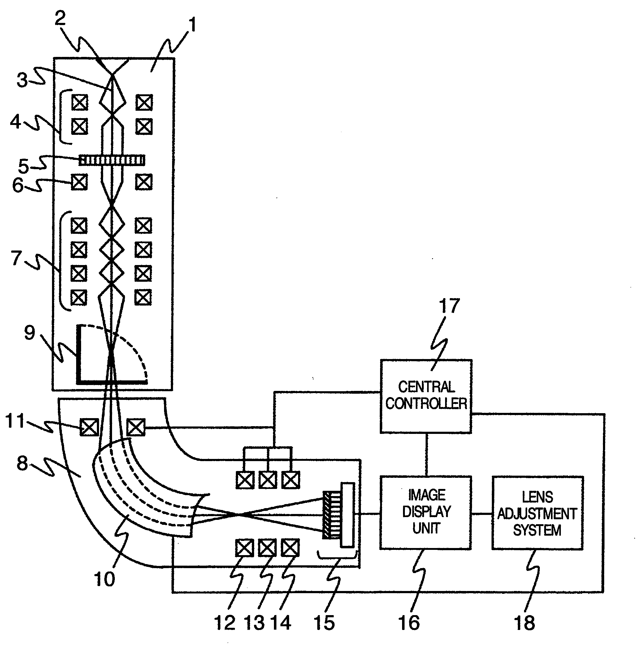
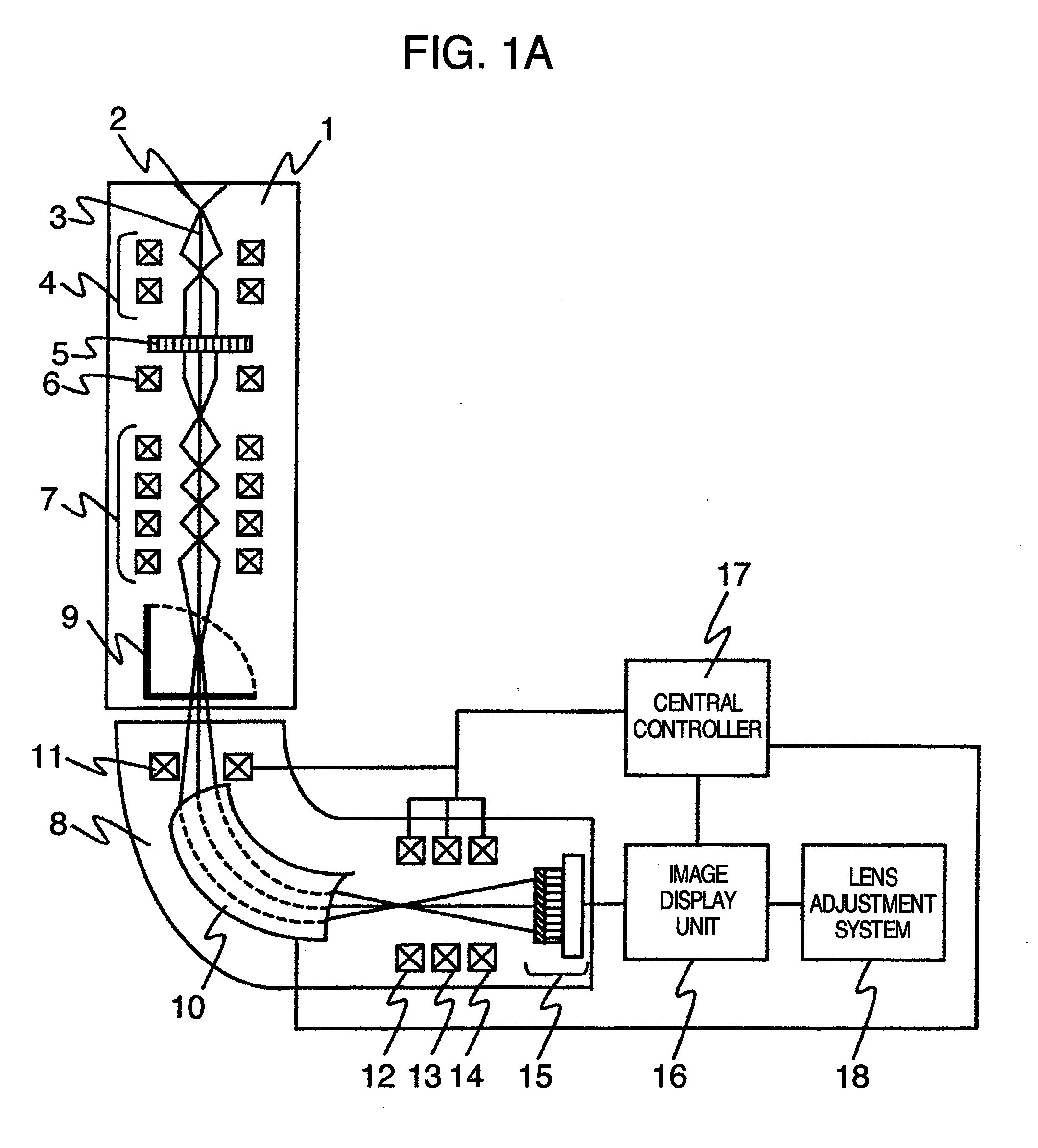
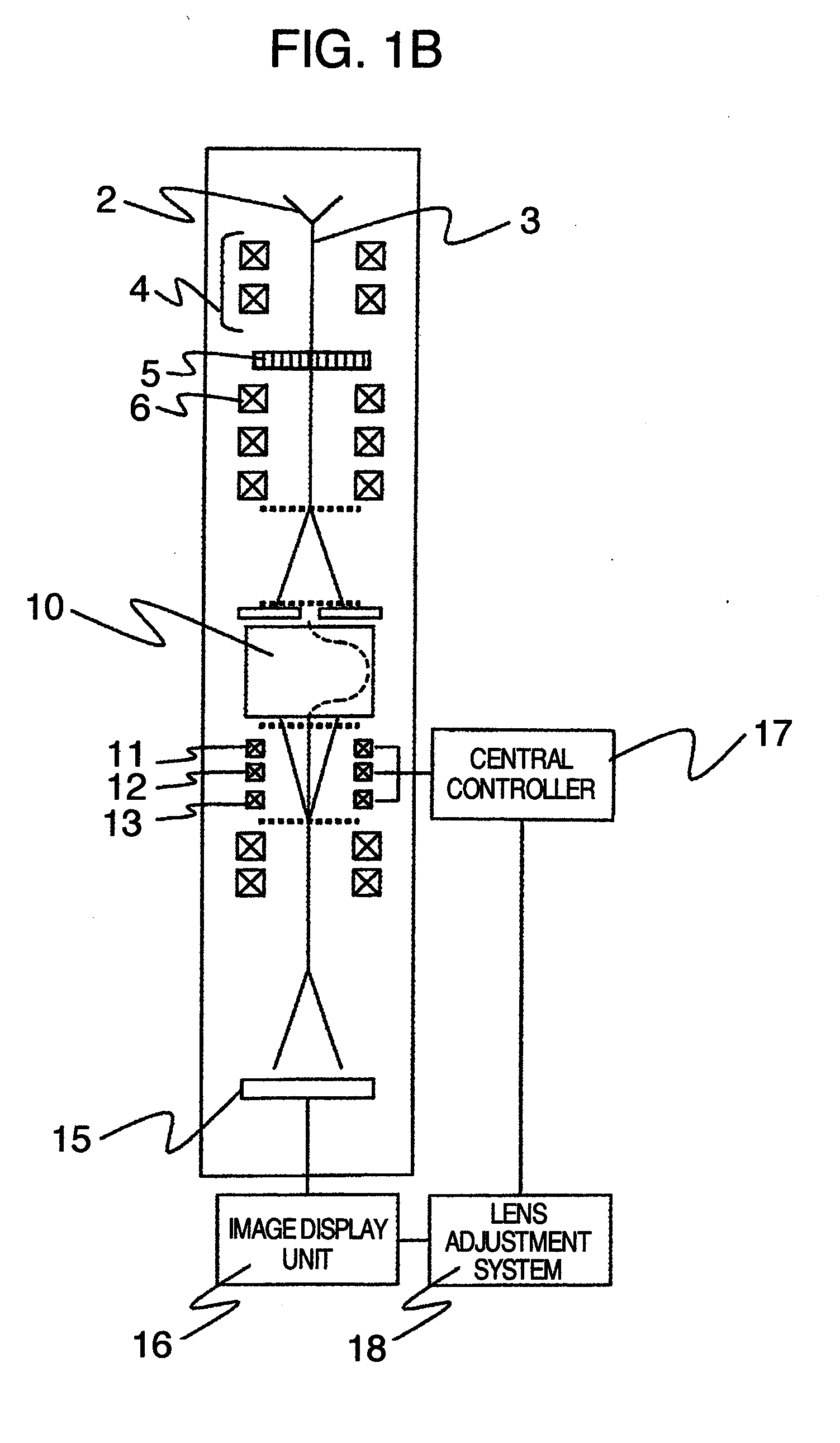
[0012]To accomplish the above object, according to the present invention, an electron microscope having an electron spectrometer adapted to acquire an electron energy loss spectrum or a two-dimensional element distribution image comprises an electron spectrometer controller for adjusting a plurality of lenses provided in the electron spectrometer, the controller being operative to set conditions of the individual lenses on the basis of a parameter design method using exciting conditions of the individual lenses as parameters. Thus, in acquiring an electron energy loss spectrum and a two-dimensional element image distribution by means of the electron spectrometer, optimum conditions of the plurality of lenses can be set highly efficiently and highly accurately.
[0019]According to the present invention, the electron microscope can be provided which can adjust highly efficiently and highly accurately the optimum conditions of the plurality of lenses the electron spectrometer has and can measure energy with high resolution. Further, according to the above lens adjustment method and system for the electron spectrometer, the lenses can be adjusted within a short period of time with easy-to-operation capability.

Problems solved by technology

In addition, in case the electron beam intensity cannot always be constant owing to instability of an electron source or variations in external disturbance, it is difficult to place the energy resolution of spectrum in optimal condition by determining the maximum value of electron beam intensity.
As described above, each of the techniques disclosed in JP-A-2003-151478 and JP-A-2000-285845 is directed to an adjustment method for optimization of the energy resolution in the electron spectrometer attached to the electron microscope but has difficulties in making adjustments of the individual lenses at a time.

Method used


Image

  • Electron microscope with electron spectrometer
  • Electron microscope with electron spectrometer
  • Electron microscope with electron spectrometer

Examples


Embodiment Construction

[0033]An electron microscope of the present invention will now be described in greater detail.

[0034]An electron energy loss spectrum can principally be classified into a zero-loss spectrum that does not loose energy during passage of an electron beam through a specimen, a plasmon loss spectrum acquired by exciting a valance band electron and loosing energy and a core electron excitation loss spectrum acquired by exciting a core electron and loosing energy. In the core electron excitation loss (core loss) spectrum, a fine structure can be observed in the vicinity of the absorption edge. The structure is referred to as an energy loss near-edge structure (ELNES) and has information in which an electron state and a chemical-bonding state of a specimen are reflected. Furthermore, an energy loss value (absorption edge position) is specific to an element and therefore, can be analyzed qualitatively. In addition, information related to peripheral coordination of an element of interest can b...


PUM


Abstract

A lens adjustment method and a lens adjustment system which adjust a plurality of multi-pole lenses of an electron spectrometer attached to a transmission electron microscope, optimum conditions of the multi-pole lenses are determined through simulation based on a parameter design method using exciting currents of the multi-pole lenses as parameters.

Description

BACKGROUND OF THE INVENTION[0001]The present invention relates to an electron microscope with an electron spectrometer capable of acquiring an electron energy loss spectrum and a two-dimensional element distribution image and more particularly, to an electron microscope with a lens adjustment system capable of adjusting the electron spectrometer highly efficiently and highly accurately and to a lens adjustment method as well.[0002]With advancement of fineness of working dimensions of a silicon semiconductor, a magnetic device and the like and with advancement of their high-grade integration, problems of degradation in device characteristics and reduction in reliability have now become more serious than heretofore in the course of developing a new process and of a mass production process. In recent years, for the purpose of getting to the root of causes of the faults as above, a spectroscopic analysis / two-dimensional distribution analysis based on electron energy loss spectroscopy (E...

Claims


Application Information

Patent Timeline
IPC IPC(8): G01N23/00
CPCH01J37/05H01J37/224H01J37/26H01J37/265H01J2237/0492H01J2237/30433H01J2237/10H01J2237/153H01J2237/24485H01J2237/2485H01J2237/057
Inventor TERADA, SHOHEITANIGUCHI, YOSHIHUMIKAJI, KAZUTOSHI
Owner HITACHI HIGH-TECH CORP
Learn More