
Smart medical compliance method and system

a medical compliance and smart technology, applied in the field of smart medical compliance methods and systems, can solve problems such as errors, drug administration, and new technologies

Inactive Publication Date: 2009-02-12
KYAB LULEA
View PDF43 Cites 546 Cited by
  • Summary
  • Abstract
  • Description
  • Claims
  • Application Information

AI Technical Summary

Benefits of technology

[0042]Preferably the portable hand held computer has at least a part of the electronics thereof juxtaposed with the RFID Reader. So that the RFID tag of the care provider is part of the Hand held computer. Or the care provider may have a separate RFID for ensuring authorized use of the Hand held computer.
[0043]Preferably the medical device at the POC has an RFID tag juxtaposed with interfacing electronics forming at least part of the control device (perhaps RFID System on a Chip).
[0044]Preferably the control device is arranged to disable operation of the operable element. Although as an alternative it may merely provide visual or other indication to the care provider that the computer system indicates that the operation is proper so that the care provide may proceed.

Problems solved by technology

Some of the more prominent errors are erroneous patient identification, drug administration, and medication administration recording.
In addition to POC errors, there are other sources of errors including prescription, transcription, and dispensing.
These technologies are not new and have been in commercial use for well over twenty years.
One of the problems with early adoption of both RFID and barcodes is that they are inherently submissive, allowing for identification with little or no support for interactivity and automation.

Method used


Image

  • Smart medical compliance method and system
  • Smart medical compliance method and system
  • Smart medical compliance method and system

Examples


embodiment 226

[0179]In the series of Figures numbered 2 is a diagram illustrating Smart Screw Clamp—Mechanical Instance (slide on type 226 and hinged type 230). FIG. 2A shows the tubing 200 encased by the RFID screw clamp consisting of the RFID 222, manual pinch-off screw actuator 214, an optional lock / unlock mechanism 218, encased in a housing 222, including a visual / audio indicator 208 and associated electronics 204. In the hinged embodiment the hinge 234 allows the clamp to be clamped onto the tube 200 while in slide on embodiment 226 the tube 200 is slid into the clamp housing 222.

[0180]In the series of Figures numbered 3 is a diagram illustrating Smart Screw Clamp—Electromechanical Instance (slide on type 258 and hinged type 262). FIG. 3A shows the tubing 200 encased by the RFID screw clamp consisting of the RFID 212, electromechanical pinch-off screw 246 (with lock / unlock mechanism), encased in a housing 242, including a visual / audio indicator 208 and associated electronics 204. In the hing...

embodiment 760

[0264]In the series of Figures numbered 32 is a diagram illustrating possible removable thumb-rest implementations. FIG. 32A illustrates a press fit embodiment 748 where the plunger shaft 744 is pressed into the thumb rest 740. FIG. 32B illustrates an insert and rotate embodiment 760 where the plunger shaft 756 is fit into the thumb rest 752. The thumb rest is retained in position by a key and slot mechanism.

[0265]In the series of Figures numbered 33 is a diagram illustrating a smart syringe: fail-safe RFID with Intersticed control device 764. FIG. 33 illustrates the typical syringe 564 that can be coupled via a standard couple 768 to the RFID control valve inclusive of an RFID 212 and flow control mechanism. The RFID control valve is also capable of being coupled to the syringe accessory 588 (needle, tube, channel, etc.)

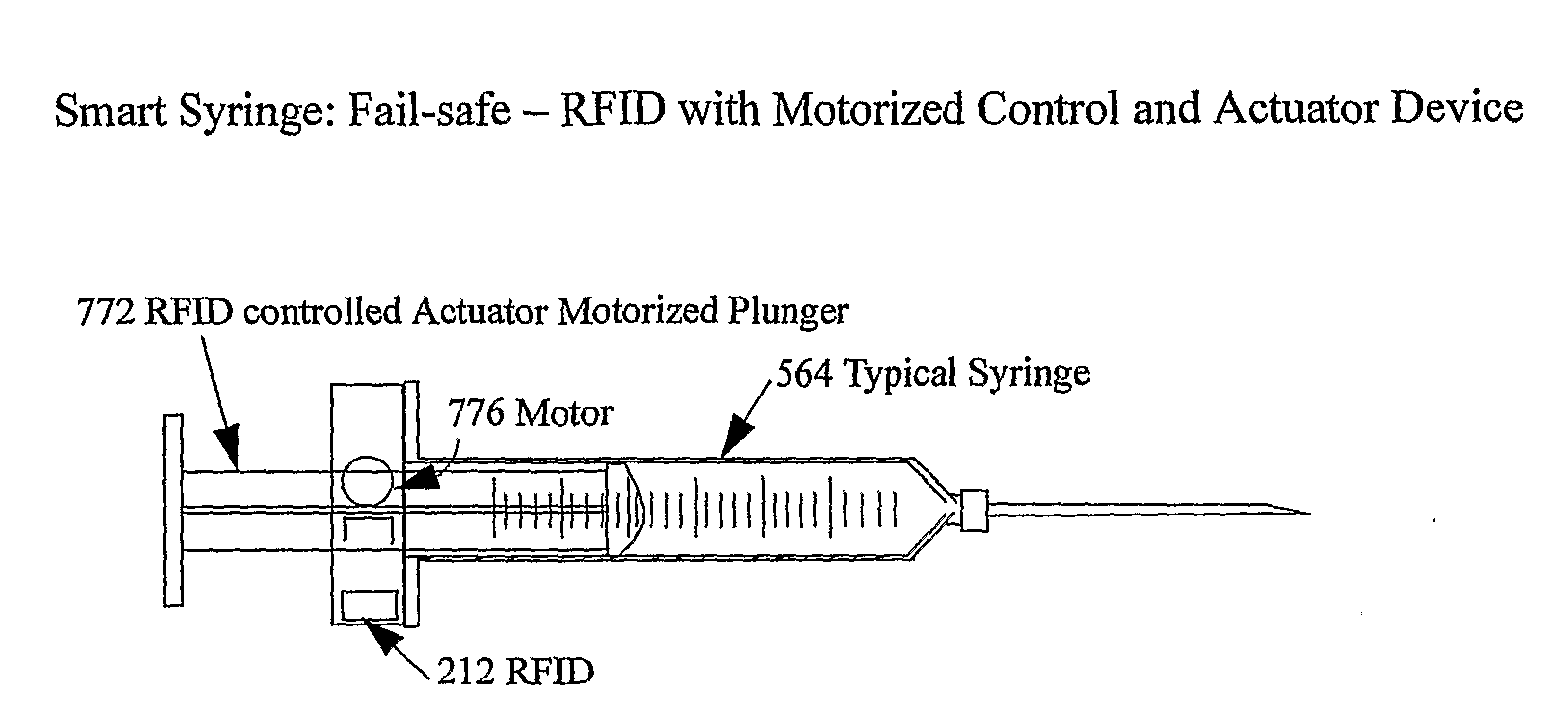
[0266]In the series of Figures numbered 34 is a diagram illustrating a smart syringe: fail-safe RFID with motorized control and actuator device. FIG. 34A illustrate...


PUM


Abstract

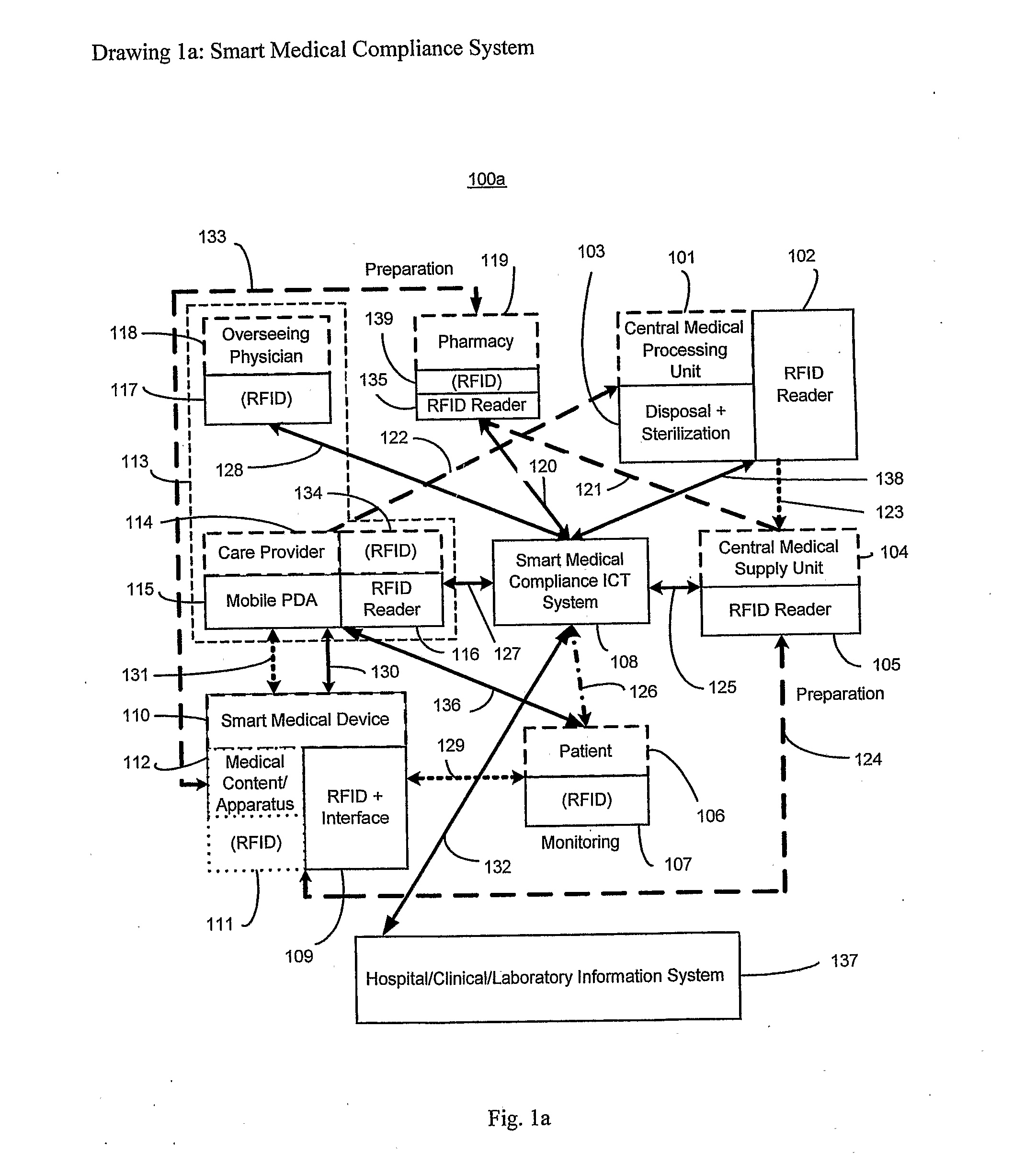
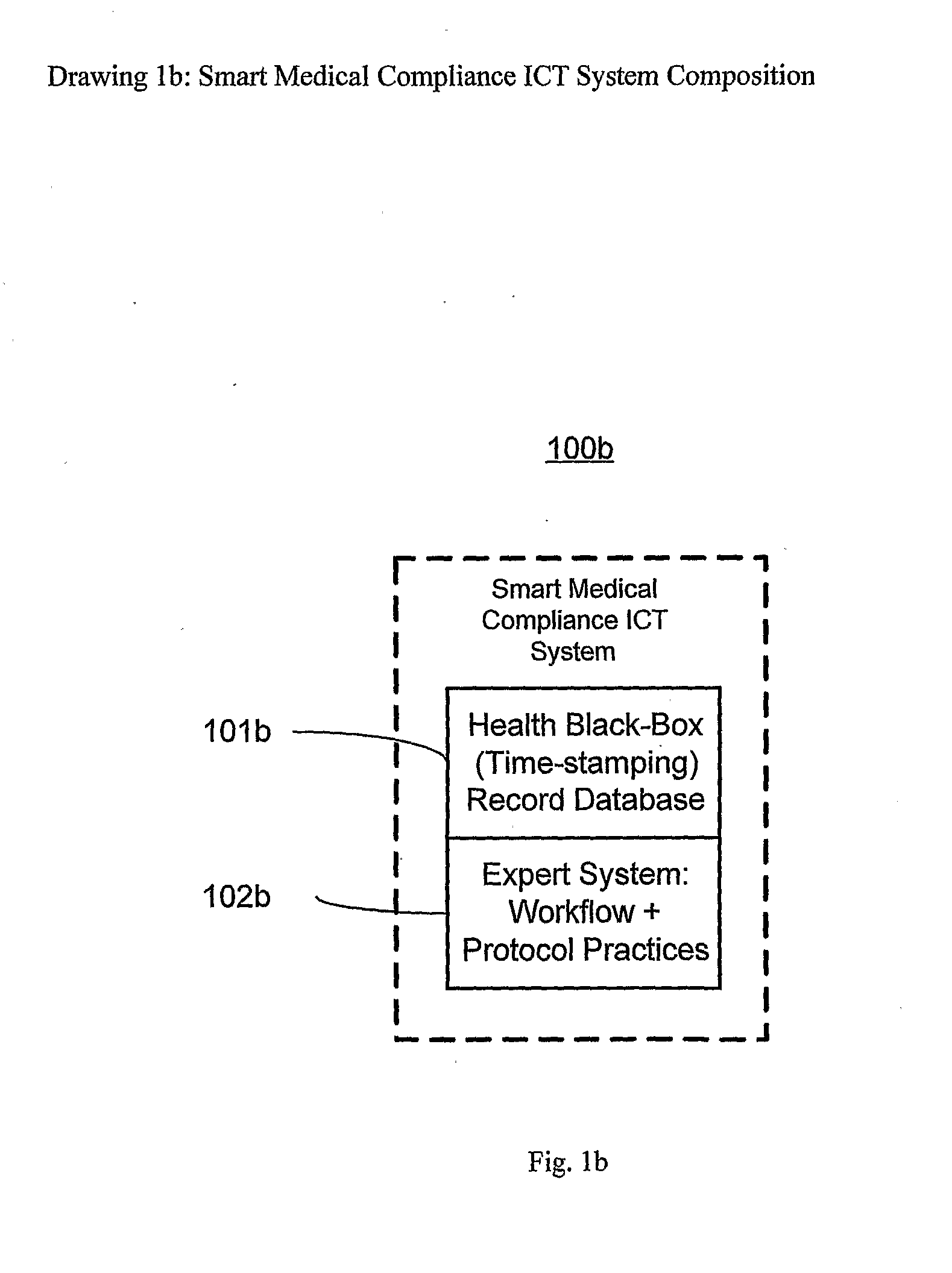
The smart medical compliance method and system invention prevents adverse drug events through the use of protocols that uniquely identifies the patient, care provider, medication and / or medical device that is to be used with radio frequency identification (RFID). The RFID devices incorporate fail-safe locks or indicators that prevent the inadvertent or unauthorized use of medication, medical devices, or medical supplies. The system corroborates, patient, the care provider, the medical device, and the manner in which it is to be used, and authorizes the action to be undertaken through an interface on a personal digital assistant PDA over a wireless communication channel. The system also timestamps events in the equivalent of a medical black box such that records may be kept to further improve patient care and allow an analysis of procedures. In addition, the system includes interfaces to medication preparation and safe disposal. A number of smart devices that interact with the system are also described. These include smart medical containers, smart clamps, smart valves, smart syringes, smart couplers, smart pipettes, and a host of other point of care devices.

Description

[0001]This invention relates to a system for providing patient care at a point of care (POC).BACKGROUND OF INVENTION[0002]Currently there is a heightened demand for improvements in patient point of care (POC). Errors and other incidents are inevitable in complex systems, and hence, mitigating medical errors through the use of technology and protocols via systems engineering is desirable. Over the past several years there has been increased emphasis on the reporting and analysis of POC errors. Some of the more prominent errors are erroneous patient identification, drug administration, and medication administration recording.[0003]It is estimated that approximately 36% of adverse drug events occur at the patient POC while only 2% are intercepted [JAMA, 1995]. In addition to POC errors, there are other sources of errors including prescription, transcription, and dispensing. It is recognized that any effective system or technology for improving POC will need to be integrated within the ...

Claims


Application Information

Patent Timeline
Patent Type & Authority Applications(United States)
IPC IPC(8): A61M5/31H04Q5/22
CPCA61M5/31505A61M39/22A61M39/283A61M39/284A61M39/287G06F19/322A61M2205/6018A61M2205/6054G06F19/3468G06Q10/10G06Q50/22A61M2005/3151G16H10/60G16H20/00
Inventor PODAIMA, BLAKE
Owner KYAB LULEA
Learn More