Robust mosaicing method. notably with correction of motion distortions and tissue deformations for a vivo fibered microscopy

a mosaicing method and mosaicing technology, applied in the field of mosaicing algorithms, can solve the problems of creating additional small non-rigid deformations and motion artifacts

Active Publication Date: 2009-02-12
INRIA NATIONAL INSTITUTE FOR RESEARCH IN COMPUTER SCIENCE AND CONTROL +1
View PDF5 Cites 41 Cited by
  • Summary
  • Abstract
  • Description
  • Claims
  • Application Information

AI Technical Summary

Problems solved by technology

This induces motion artifacts when the optical microprobe moves with respect to the imaged tissue.
Furthermore, the interaction of the contact optical microprobe with the soft tissue creates additional small non-rigid deformations.

Method used


Image

  • Robust mosaicing method. notably with correction of motion distortions and tissue deformations for a vivo fibered microscopy
  • Robust mosaicing method. notably with correction of motion distortions and tissue deformations for a vivo fibered microscopy
  • Robust mosaicing method. notably with correction of motion distortions and tissue deformations for a vivo fibered microscopy

Examples


Embodiment Construction

[0054]Although the invention is not limited to this, the method according to the present invention implemented in a confocal microscope with laser scanning in fibre mode will now be described.

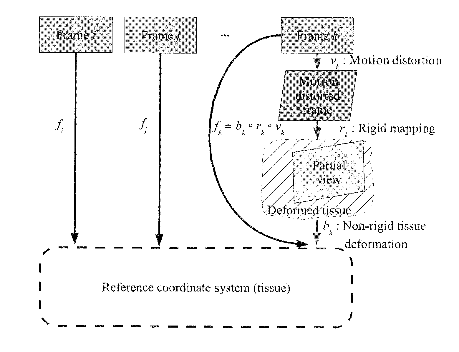
[0055]The scanning of the laser can be decomposed into a fast horizontal sinusoidal component and a slow linear uniform vertical component. Horizontally, the imaging is done only on the central part of the trajectory, where the spot velocity is maximal and nearly constant. Since in this part, the spot horizontal velocity Vx (>5 m / s) is several orders of magnitude higher than the spot vertical velocity Vy (˜2 mm / s), we assume that the horizontal spot velocity is infinite.

[0056]An interesting point of scanning imaging devices is that the output image is not a representation of a given instant, but a juxtaposition of points acquired at different times. Consequently, if the flexible microprobe moves with respect to the imaged tissue, what we observe is not a frozen picture of the tissue, but a skew...


PUM


Abstract

The present invention concerns a mosaicing method taking into account motion distortions, irregularly sampled frames and non-rigid deformations of the imaged tissue. The invention relates to a method for mosaicing frames from a video sequence acquired from a scanning device such as a scanning microscope, the method comprising the steps of:a) compensating for motion and motion distortion due to the scanning microscope,b) applying a global optimisation of inter-frame registration to align consistently the framesc) applying a construction algorithm on the registered frames to construct a mosaic, andd) applying a fine frame-to-mosaic non rigid registration.The method is based on a hierarchical framework that is able to recover a globally consistent alignment of the input frames, to compensate for the motion distortions and to capture the non-rigid deformations.

Description

BACKGROUND OF THE INVENTION[0001]The present invention relates generally to mosaicing algorithm, and relates more particularly to a method for mosaicing frames from a video sequence acquired from a fibered confocal scanning device.[0002]Fibered confocal microscopy (FCM) is based on the principle of confocal microscopy which is the ability to reject light from out-of-focus planes and provide a clear in-focus image of a thin section within the sample. This optical sectioning property is what makes the confocal microscope ideal for imaging thick biological samples. The adaptation of a fibered confocal microscope for in vivo and in situ imaging can be viewed as replacing the microscope objective by a flexible microprobe of adequate length and diameter in order to be able to perform in situ imaging. For such purpose, a flexible fiber bundle is used as the link between the scanning device and the miniaturized microscope objective (see FIG. 1). The Celivizio©, developed by Mauna Kea Techno...

Claims


Application Information

Patent Timeline
Patent Type & Authority Applications(United States)
IPC IPC(8): G06K9/00
CPCG02B21/367G06K9/00134G06T2207/10056G06T7/0034G06T3/4038G06T7/35G06V20/693
Inventor VERCAUTEREN, TOMPERCHANT, AYMERICAYACHE, NICHOLASPENNEC, XAVIERMALANDAIN, GREGOIRE
Owner INRIA NATIONAL INSTITUTE FOR RESEARCH IN COMPUTER SCIENCE AND CONTROL
Why Eureka
Try Eureka