
Apparatus, method and computer program for spectroscopic measurements and analysis

Inactive Publication Date: 2009-02-12
WIDENGREN JERKER
View PDF3 Cites 13 Cited by
  • Summary
  • Abstract
  • Description
  • Claims
  • Application Information

AI Technical Summary

Benefits of technology

[0020]The proposed solutions make it possible to interrogate long-lived, transient, photo-induced states in a highly parallelised, high-throughput manner with high sensitivity.
[0024]Likewise, beating patterns can be generated if the resulting fluorescence is a product of the excitation field and one or several of the additional radiation fields. With spatial or temporal modulation of these fields, spatial and temporal beating patterns can appear, with frequencies given by the differences of the excitation and additional radiation fields, but also influenced by the transient state kinetics. Changes in the transient state kinetics can possibly generate large relative changes in the beating frequencies, which thus may serve as a possible readout of the transient state parameters.
[0029]The invention can provide novel transient state parameters in addition to the “traditional” fluorescence parameters (intensity, wavelength of excitation and emission, fluorescence lifetime, and polarisation). The increased number of independent parameters can offer an enhanced possibility of identifying and proving the presence of disease-specific molecules, or molecular interactions, within for instance an array of samples.

Problems solved by technology

In addition to the mentioned disadvantages, none of the above described known methods and technologies provide an accurate and reliable method for obtaining time-resolved information with a parallel read-out of triplet states, as well as other information relating to the levels and rates by which transient photoinduced states of fluorophores are populated and depopulated.

Method used


Image

  • Apparatus, method and computer program for spectroscopic measurements and analysis
  • Apparatus, method and computer program for spectroscopic measurements and analysis
  • Apparatus, method and computer program for spectroscopic measurements and analysis

Examples


first embodiment

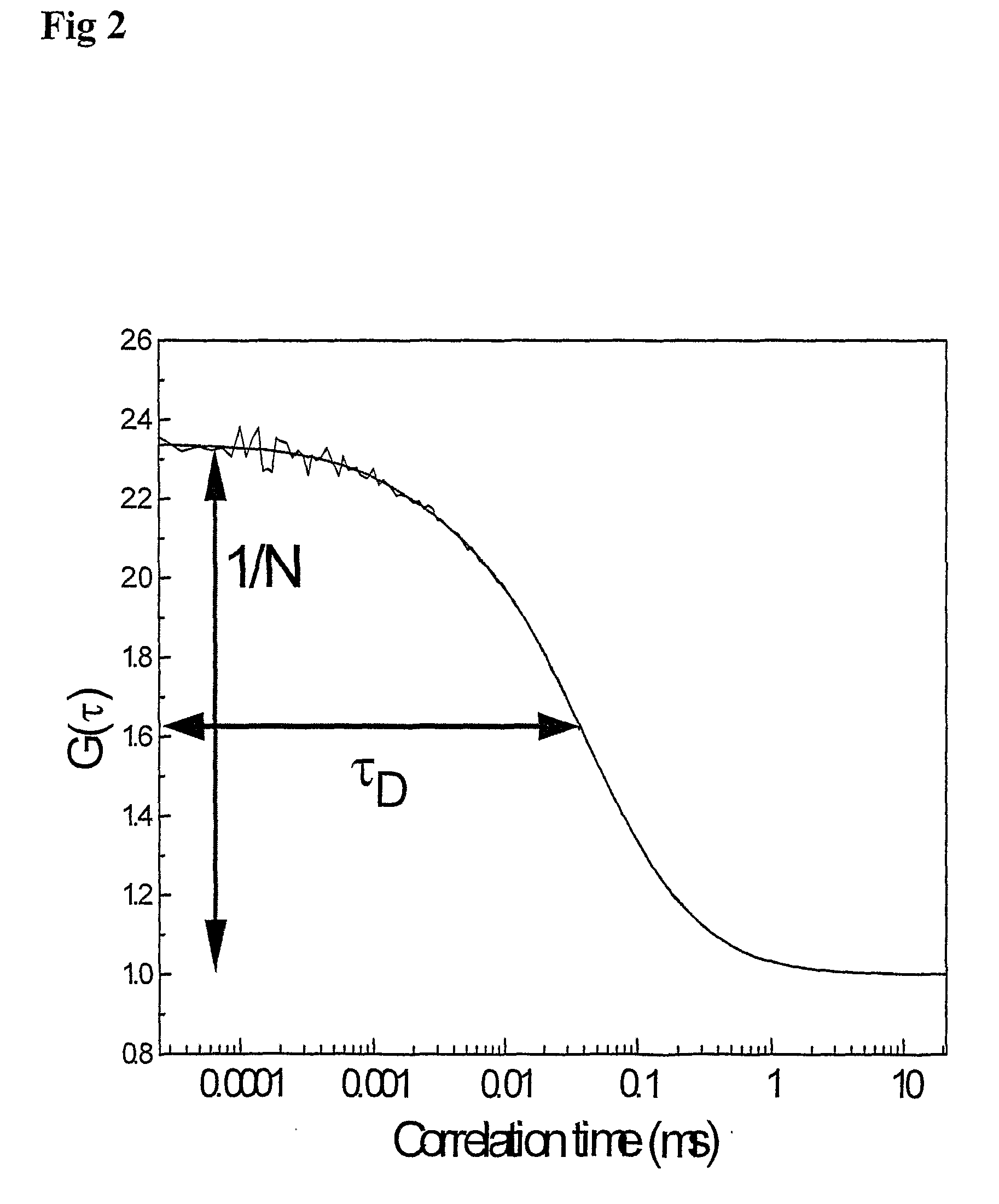
[0048]In a first embodiment according to the present invention, control, manipulation, and monitoring of Texc is done by periodic excitation with different pulse durations and excitation intensities. As previously mentioned, an FCS curve reflects the probability of detecting a fluorescence photon from the molecule under investigation, given that a fluorescence photon was emitted from it at correlation time, π=0. Looking at FIG. 4, the fluorophore must be in the singlet entity at τ=0 (since it then emitted a photon). The first relaxation process in the FCS curve reflects the transit of the fluorophore from the singlet entity (S0 or S1) into a steady state, where it has a probability of Y to be in the triplet state (thus the lower amplitude=probability to emit a photon). In other words, at τ-0, the probability to find the fluorophore in a singlet state (available for fluorescence) is S0+S1=100%, and the fluorophore is fully fluorescent. At τ>>τT the fluorophore has relaxed into a stea...

second embodiment

[0054]In accordance with the present invention, a solution for how to more reliably probe the extent of triplet state quenching is proposed (see FIG. 10). The triplet state population can be strongly enhanced by addition of quenchers, which by the so called heavy-atom effect enhance the rate of intersystem crossing, kISC. This can be very clearly seen in FCS measurements as a prominent increase in the triplet population. However, we have observed that for some fluorophore / quencher combinations, the triplet decay rate, kT, is far more enhanced than the intersystem crossing. Depending on if kISC or kT is most strongly increased, the triplet population will either markedly increase or decrease upon addition of a quencher, if the excitation intensity is high enough to produce a steady-state triplet population in the first place (see FIG. 10). This is hereafter referred to as differential quenching. Consequently, using two different fluorophores emitting in different wavelength regions, ...

third embodiment

[0055]In accordance with the present invention, FRET is proposed in combination with application of differential quenching. As can be seen in equations 2 and 3 above, both T and τT depend on the excitation rate k12. This dependence remains, no matter the mode of excitation Consequently, if the excitation takes place via FRET, the triplet state parameters of the acceptor can be used to determine the rate of FRET-mediated excitation from the donor, and hence the FRET efficiency E. While the triplet state population of the acceptor should preferentially be prominent, in order to clearly see also smaller changes in E, the triplet population of the donor should be low to minimize interference in the transfer of excitation energy to the acceptor. The proposed solution is to use differential quenching, where the triplet population of the donor is decreased, while that of the acceptor is increased.

[0056]When applying the combination of FRET and differential quenching, the following advantag...


PUM


Abstract

The present invention relates to a spectroscopic method and associated apparatus and computer program for measuring and analysing intensities of fluorescent molecules excited by an energy pulse. The method includes the steps of: a) generating a transient state build-up in the fluorescent molecules by means of an excitation pulse, within which pulse repetitive excitation-emission cycles are induced in the fluorescent molecules between their ground, typically singlet (So) and excited, typically singlet (SO states, resulting also in transition from S] to the transient state, b) relaxation of population of the transient state by transition back to the ground state in a time period following directly after the excitation pulse, c) determination of the transient state population by recording the fluorescence. The invention is characterised by varying pulse characteristics from one sequence of pulses to the next so as to circumvent the need of time-resolution in the detection.

Description

TECHNICAL FIELD OF THE INVENTION[0001]The present invention relates to an apparatus, spectroscopic method and a related computer program for measuring and analysing intensities of fluorescent molecules excited by an energy pulse. More in detail, the invention relates to generation of a transient state build-up in a fluorescent material by means of an excitation pulse, and relaxation back to ground state in a time period with no excitation. The transient-state properties are determined from the dependence of fluorescence intensity on the durations of periods with and without excitation.BACKGROUND OF THE INVENTION[0002]There are several known ways of measuring and obtaining characteristics and various transient-state properties in fluorescent molecules. One way is the so-called fluorescence correlation spectroscopy (FCS) (see J. Widengren and Ü. Mets p. 69-119 in “Single Molecule Detection in Solution—methods and applications” VCH-Wiley Verlag, Berlin, 2002). The use of FCS and relate...

Claims


Application Information

Patent Timeline
IPC IPC(8): G01N21/64
CPCG01N21/00G01N21/6408G01N2021/6441G01N21/6452G01N2021/6432G01N21/6428
Inventor WIDENGREN, JERKER
Owner WIDENGREN JERKER
Learn More