Electronic component and method for manufacturing the same
a technology of electronic components and resistive films, applied in the field of electronic components, can solve the problems of insufficient space for electroconductive pastes applied by the second and subsequent screen printing, high cost of preparing the corresponding screen plate for each, and insufficient resistance of resistive film coatings, etc., to achieve stable resistance, reduce the variation in resistance of the resulting resistive film, and increase the mixing time of ink
- Summary
- Abstract
- Description
- Claims
- Application Information
AI Technical Summary
Benefits of technology
Problems solved by technology
Method used
Image
Examples
embodiment 1
[0055] Embodiment 1 will now be described with reference to FIGS. 1 to 3.
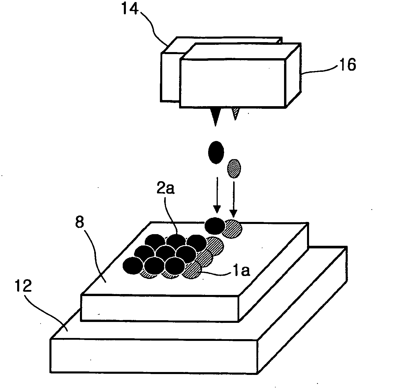
[0056]An ink jet printer 10 used for printing a pattern intended for a resistive film (resistor element) will first be described with reference to the schematic representation shown in FIG. 1.
[0057]The ink jet printer 10 generally includes a movable table 12 on which a base material 8 is placed, a plurality of (for example, three) ink jet heads 14, 16, and 18, and a controller 11 controlling the entire apparatus.
[0058]The movable table 12 is driven in the X direction designated by reference numeral 23 by a motor 22, in the Y direction designated by reference numeral 25 by another motor 24, and in the θ direction designated by reference numeral 27 (around on the Z axis perpendicular to the x and the y axis) by still another motor 26. The drive of the movable table 12 by the motors 22, 24, and 26 is controlled by the controller 11. The movable table 12 may be able to move in a direction other than the X, Y, and θ...
embodiment 2
[0091] Embodiment 2 will now be described with reference to FIGS. 4 and 5.
[0092]In Embodiment 2 as well, an ink jet printer is used for printing.
[0093]As schematically shown in FIG. 4, resistive inks ejected from the respective ink jet heads 14 and 16 are simultaneously printed at substantially the same position on a base material 8 disposed on a movable table 12. In this instance, some or all of the dots 1a of resistive ink 1 ejected from the ink jet head 14 and some or all of the dots 2a of resistive ink 2 ejected from the ink jet head 16 are disposed one on top of the other. Also, the dots 2a of resistive ink 2 are disposed on the dots 1a of resistive ink 1 before the dots 1a are dried so that the dots 1a and 2a of resistive inks 1 and 2 are mixed. In order to accelerate the mixing, supersonic waves may be applied. Part of the constituents of resistive ink 1 and part of the constituents of resistive ink 2 may chemically react with each other or form an alloy by the mixing.
[0094]P...
embodiment 3
[0104] Embodiment 3 will now be described with reference to FIG. 6.
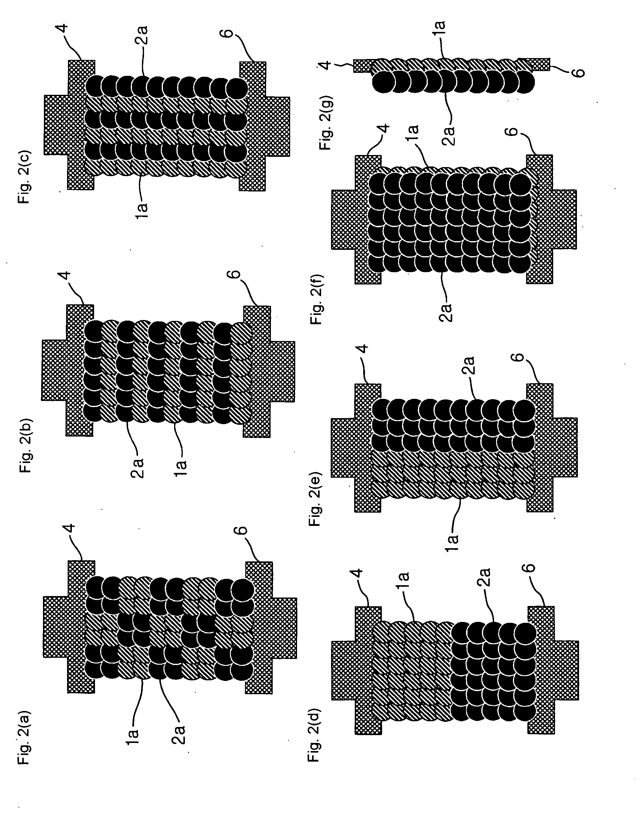
[0105]The pattern shown in the plan view of FIG. 6(a) includes first groups disposed at the terminal 4 side and second groups disposed at the terminal 6 side, like the pattern shown in FIG. 2(d). The first group 1s is defined by a plurlity of (4 by 6 in the figure) dots 1a of resistive ink 1 arranged in a rectangular manner, and the second group 2s is defined by a plurality of (4 by 6 in the figure) dots 2a of resistive ink 2 arranged in a rectangular manner. Third groups and fourth groups are disposed in a staggered manner like the pattern shown in FIG. 2(a) in a region 5s between the first group is and the second group 2s. Each third group is defined by a plurlity of dots 1a of resistive ink 1 as in the pattern shown in FIG. 2(a), and each fourth group is defined by a plurality of dots 2a of resistive ink 2. The dots 1a and 2a overlap each other and thus the first to the fourth group are continuous.
[0106]The patter...
PUM
| Property | Measurement | Unit |
|---|---|---|
| Fraction | aaaaa | aaaaa |
| Temperature | aaaaa | aaaaa |
| Electrical resistance | aaaaa | aaaaa |
Abstract
Description
Claims
Application Information
 - R&D
- Intellectual Property
- Life Sciences
- Materials
- Tech Scout
- Unparalleled Data Quality
- Higher Quality Content
- 60% Fewer Hallucinations
Browse by: Latest US Patents, China's latest patents, Technical Efficacy Thesaurus, Application Domain, Technology Topic, Popular Technical Reports.
© 2025 PatSnap. All rights reserved.Legal|Privacy policy|Modern Slavery Act Transparency Statement|Sitemap|About US| Contact US: help@patsnap.com


