
Time-Multiplexed-Capacitor DC/DC Converter with Multiple Outputs

a technology of multi-capacitor and converter, which is applied in the direction of dc-dc conversion, power conversion system, instruments, etc., can solve the problems of loss of efficiency, and the voltage differential between the charge pump and the charge pump is lower

Active Publication Date: 2009-02-12
ADVANCED ANALOGIC TECHNOLOGIES INCORPORATED
View PDF6 Cites 93 Cited by
  • Summary
  • Abstract
  • Description
  • Claims
  • Application Information

AI Technical Summary

Benefits of technology

"This patent describes a new method for generating multiple output voltages from a single supply using a time-multiplexed-capacitor converter. This new method allows for the simultaneous production of positive and negative output voltages, providing more flexibility and versatility in applications that require multiple output voltages. The new method uses a switching network to connect the flying capacitors in different configurations, resulting in different modes of operation. These modes include a first mode where the flying capacitors are connected in series with the positive electrode, a second mode where the negative electrodes are connected, and a third mode where both the positive and negative electrodes are connected. The new method also allows for the simultaneous production of two positive fractional outputs and two negative fractional outputs, providing more flexibility and versatility in applications that require multiple output voltages."

Problems solved by technology

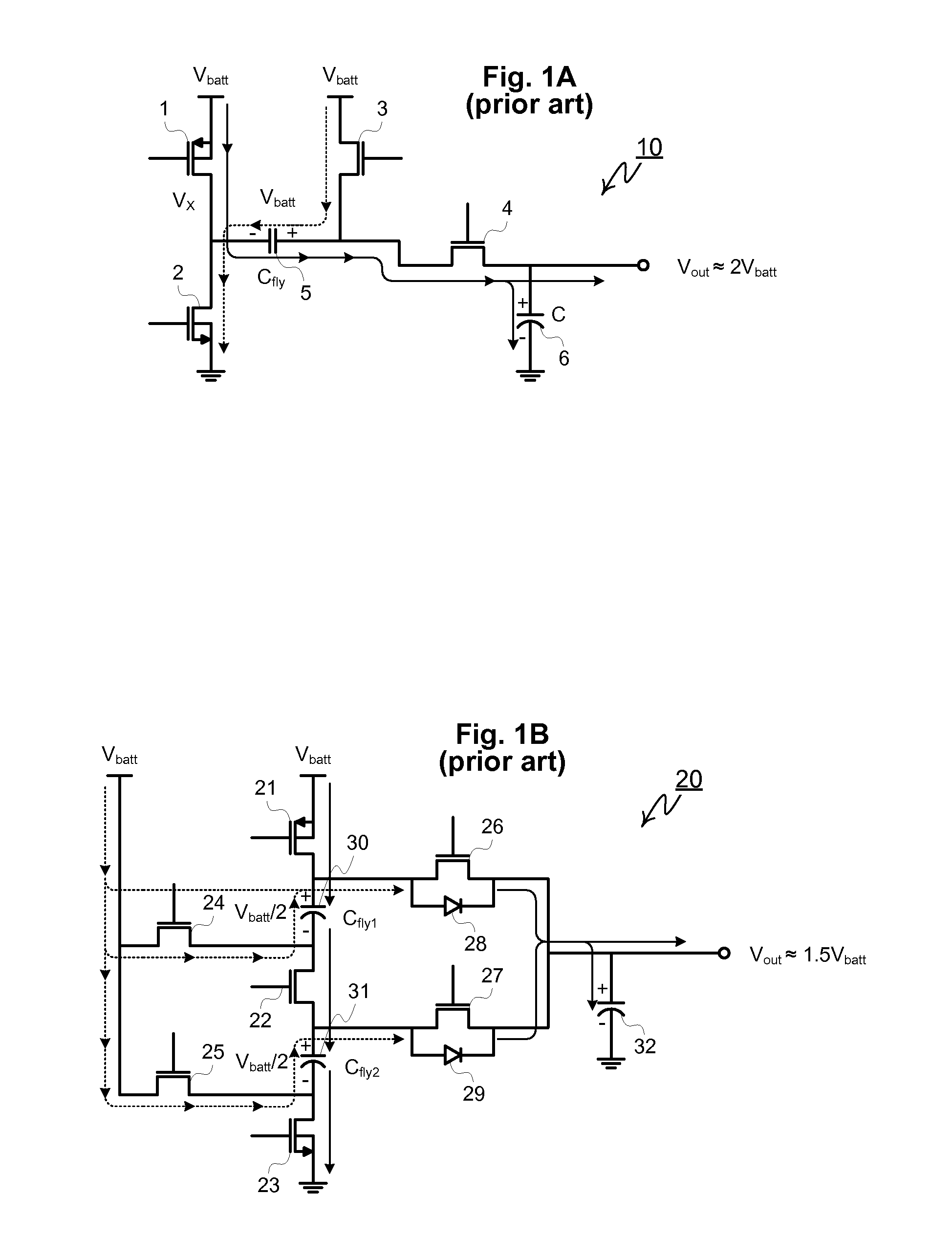
Under certain circumstances, the charge pump can operate at high conversion efficiencies, but not over the wide range of conditions that switched inductor based converters can achieve.
Any deviation between the actual output voltage Vout and the charge pump's ideal output VCP=n·Vin will result in a loss of efficiency as given by the relation
The voltage differential between the charge pump lowers efficiency by causing one of the transistors to saturate a drop the incremental business.
One common condition leading to lower efficiency in a doubler charge pump is “over-pumping” the output to a voltage higher than desired or required by the load.
As a result, its output voltage varies with its input which is undesirable in many applications.
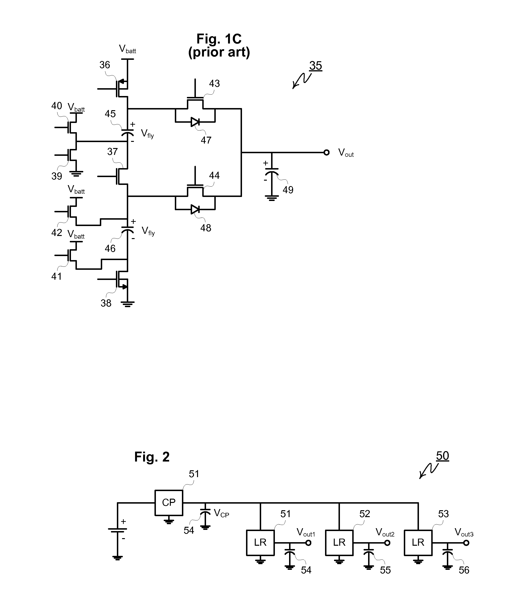
Charge Pump Efficiency Considerations: Since a charge pump's output voltage varies with its input, it is not well adapted as a power converter and must often be combined with a linear regulator connected in series with the charge pump, to limit the output voltage swing.
The term “NA” means not available, meaning that the charge pump is incapable of producing the desired output voltage over the full range of inputs.
Lower output voltages therefore suffer from lower efficiencies because the charge pump is over-pumping the voltage to too high a value.
On the other hand, a fractional charge pump cannot output all the voltages commonly desired in a system.
For example, a 1.5× charge pump cannot produce a 5V output over the full lithium ion range.
Furthermore, if both positive, i.e. above ground, and negative, i.e. below ground supply voltages are required by the system, the approach of FIG. 2 cannot be employed and multiple charge pumps are required.
In summary, the limitation of today's charge pumps is that they produce a single-voltage single-polarity output.
Such restrictions greatly limit the use of charge pumps, forcing designers to employ one charge-pump per load, undesirably increasing costs, component count, and printed circuit board space.

Method used


Image

  • Time-Multiplexed-Capacitor DC/DC Converter with Multiple Outputs
  • Time-Multiplexed-Capacitor DC/DC Converter with Multiple Outputs
  • Time-Multiplexed-Capacitor DC/DC Converter with Multiple Outputs

Examples


Embodiment Construction

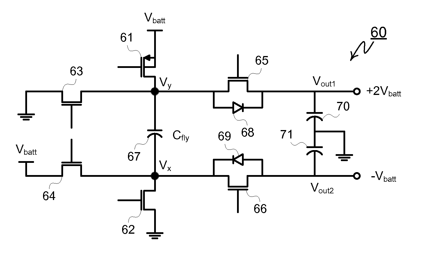
[0104]A multiple output DC-to-DC voltage converter using a new time-multiplexed-capacitor converter algorithm and related circuit topologies is herein disclosed. Unlike conventional charge pumps limited to producing a single output per charge pump, the new time-multiplexed-capacitor topology and method generates multiple voltage outputs of both positive and negative polarities from a single supply voltage or battery input. For the sake of clarity, the various embodiments of this invention are subdivided into four classes—dual polarity multiple-output converters, multiple-positive-output converters, multiple negative output converters, and re-configurable multiple-output converters.

[0105]Dual-Polarity Time-Multiplexed-Capacitor Converters: One embodiment of this invention is a time-multiplexed-capacitor converter capable of producing positive and negative output voltages simultaneously. In FIG. 3 for example, circuit 60 illustrates a time-multiplexed-capacitor dual-output converter c...


PUM


Abstract

A multiple output DC-to-DC voltage converter using a new time-multiplexed-capacitor converter algorithm and related circuit topologies is herein disclosed. One embodiment of this invention includes a flying capacitor, a first output node, a second output node, and a switching network. The switching network configured to provide the following modes of circuit operation: 1) a first mode where the positive electrode of the flying capacitor is connected to an input voltage and the negative electrode of the flying capacitor is connected to ground; 2) a second mode where the negative electrode of the flying capacitor is connected to the input voltage and the positive electrode of the flying capacitor is connected to the first output node; and 3) a third mode where the positive electrode of the flying capacitor is connected to ground and the negative electrode of the flying capacitor is connected to the second output node.

Description

BACKGROUND OF THE INVENTION[0001]Three approaches are commonly employed in implementing DC-to-DC converters—electronic circuits that converts a battery or DC voltage source to a different DC voltage. These methods comprise linear regulation, inductive switching regulators or so-called “switch-mode power supplies,” and switched capacitor converters, also known as charge pumps. Of these methods, the charge pump is valued for its simplicity, cost effectiveness, and relatively low noise operation. Under certain circumstances, the charge pump can operate at high conversion efficiencies, but not over the wide range of conditions that switched inductor based converters can achieve.[0002]The operating principle of a charge pump is straight forward comprising a charging phase and a charge transfer phase which operate in alternating sequence. As shown in FIG. 1A, prior art charge pump doubler type circuit 1 comprises four MOSFETs, a flying capacitor not attached permanently to any specific su...

Claims


Application Information

Patent Timeline
Patent Type & Authority Applications(United States)
IPC IPC(8): G05F3/08H02M1/00
CPCH02M3/07H02M2001/009G05F3/16H02M3/337H02M1/009
Inventor WILLIAMS, RICHARD K.
Owner ADVANCED ANALOGIC TECHNOLOGIES INCORPORATED
Learn More