Apparatus and Method for Efficient Communication of Producer/Consumer Buffer Status

a buffer status and communication method technology, applied in image memory management, program control, instruments, etc., can solve the problems of affecting the overall system performance, affecting the performance of producers, and requiring additional resources for updating and monitoring, and achieve the effect of low latency respons

Inactive Publication Date: 2009-02-05
INT BUSINESS MASCH CORP
View PDF6 Cites 2 Cited by
  • Summary
  • Abstract
  • Description
  • Claims
  • Application Information

AI Technical Summary

Benefits of technology

[0017]The channel interface is a message passing interface that overlaps input / output (I / O) with data processing and minimizes power consumed by synchronization. The channel facilities of the channel interface are accessed with three types of instructions: a read channel instruction, write channel instruction, and read channel count instruction which measures channel capacity. These channels may be configured as blocking or non-blocking channels. Channels that are defined as blocking channels cause the SPE to stall when accessing a channel whose channel count is zero. In this sense, the channel count indicates the number of outstanding operations that can be issued for that channel without causing the SPE to stall. Aside from blocking on channel access, an SPE program can monitor a variety of channel events using SPE interrupt facilities.
[0019]With the illustrative embodiments, the producer, running on an SPE, may read its signal notification channel(s) and operate in a blocking mode until the consumer updates the tail pointer information written to the signal notification channel(s). This provides a low-power, low-bandwidth alternative to monitoring, i.e. polling, a remote memory or register location that is local to the consumer. Further, this solution provides low latency responses for real-time systems since the SPE is automatically awoken as soon as data becomes available on the signal notification channel(s).

Problems solved by technology

As a result, this updating and monitoring requires additional resources, e.g., processor cycles, bus bandwidth, etc., within the system to support these operations.
Because of the need to utilized additional system resources, this solution may be considered too detrimental to overall system performance.
This may lead to serious degradation of performance for the producer, as the latency for reading remote locations can be several orders of magnitude worse than for main shared memory storage.

Method used


Image

  • Apparatus and Method for Efficient Communication of Producer/Consumer Buffer Status
  • Apparatus and Method for Efficient Communication of Producer/Consumer Buffer Status
  • Apparatus and Method for Efficient Communication of Producer/Consumer Buffer Status

Examples


Embodiment Construction

[0047]The following is intended to provide a detailed description of illustrative embodiments and should not be taken to be limiting of the invention itself. Rather, any number of variations may fall within the scope of the invention defined in the claims following the description.

[0048]FIG. 3 is an exemplary block diagram of a data processing system in which aspects of the present invention may be implemented. The exemplary data processing system shown in FIG. 3 is an example of the Cell Broadband Engine (CBE) data processing system. While the CBE will be used in the description of the preferred embodiments of the present invention, the present invention is not limited to such, as will be readily apparent to those of ordinary skill in the art upon reading the following description.

[0049]As shown in FIG. 3, the CBE 300 includes a power processor element (PPE) 310 having a processor (PPU) 316 and its L1 and L2 caches 312 and 314, and multiple synergistic processor elements (SPEs) 320...


PUM


Abstract

An apparatus and method for efficient communication of producer / consumer buffer status are provided. With the apparatus and method, devices in a data processing system notify each other of updates to head and tail pointers of a shared buffer region when the devices perform operations on the shared buffer region using signal notification channels of the devices. Thus, when a producer device that produces data to the shared buffer region writes data to the shared buffer region, an update to the head pointer is written to a signal notification channel of a consumer device. When a consumer device reads data from the shared buffer region, the consumer device writes a tail pointer update to a signal notification channel of the producer device. In addition, channels may operate in a blocking mode so that the corresponding device is kept in a low power state until an update is received over the channel.

Description

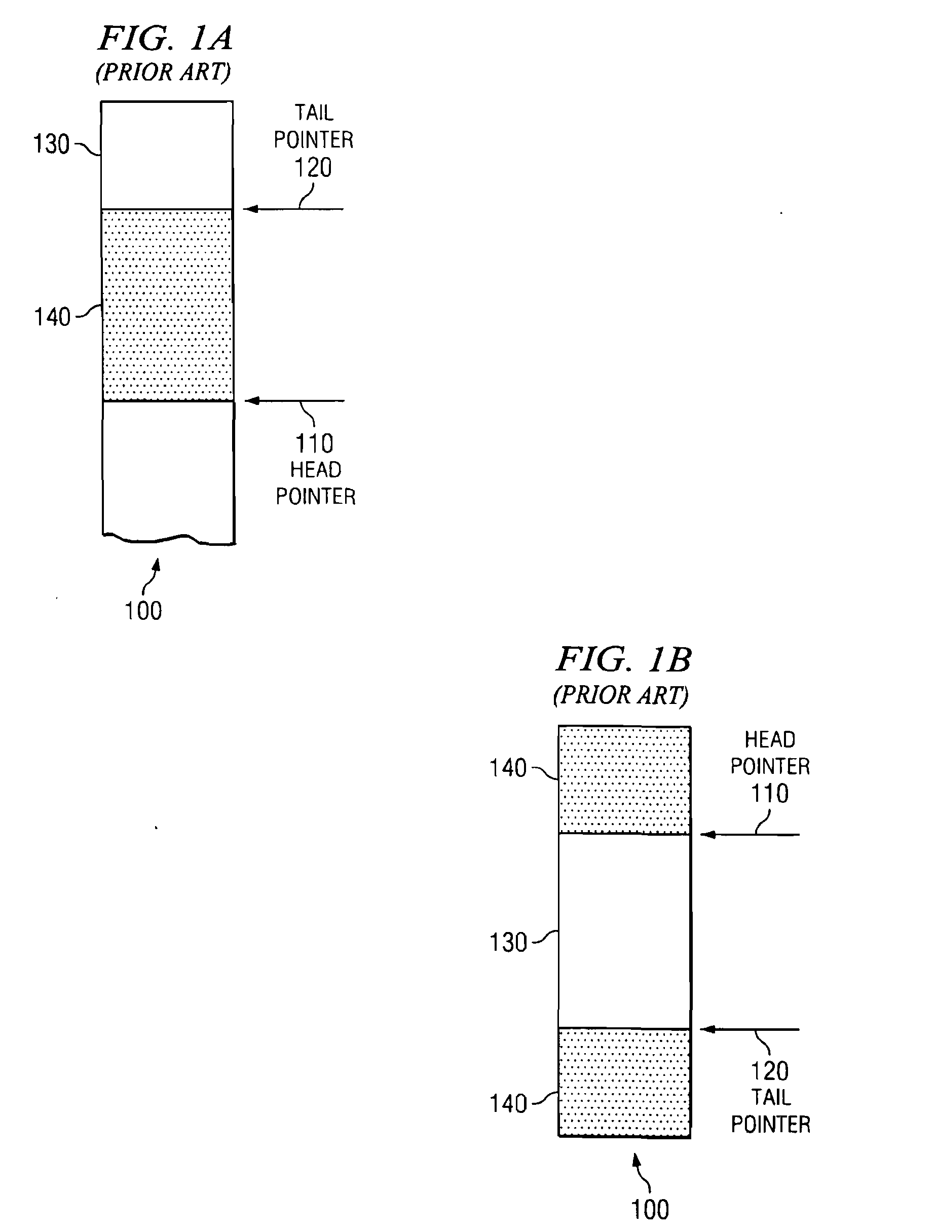
BACKGROUND[0001]1. Technical Field[0002]The present application relates generally to an improved data processing system. More specifically, the present application is directed to an apparatus and method for efficient communication of producer / consumer buffer status.[0003]2. Description of Related Art[0004]In a data processing system, one processor or device typically acts as a producer by placing data into a shared buffer while another processor or device acts as a consumer by reading and processing the data placed there by the producer. For example, consider a data processing system where a producer and a consumer, independently operating on processors or devices within the data processing system, have access to a shared data buffer region. The shared data buffer region may be located, for example, in shared system or I / O memory and is commonly accessible by both parties. In addition to the shared buffer region, two state variables are shared between the producer and consumer: a he...

Claims


Application Information

Patent Timeline
Patent Type & Authority Applications(United States)
IPC IPC(8): G06F3/00
CPCG06F15/17337
Inventor BROKENSHIRE, DANIEL A.JOHNS, CHARLES R.NUTTER, MARK R.MINOR, BARRY L.
Owner INT BUSINESS MASCH CORP
Why Eureka
Try Eureka