
Sensor system for detecting and processing EMG signals

a technology of emg signals and sensors, applied in the field of emg signals detection and processing sensors, can solve the problems of affecting the quality of life of people, affecting the ability of people to move, and images that do not provide diagnostic assessment of impairment and recovery, so as to achieve the effect of properly aligning the substra

Inactive Publication Date: 2009-02-05
DELUCA CARLO J +1
View PDF11 Cites 23 Cited by
  • Summary
  • Abstract
  • Description
  • Claims
  • Application Information

AI Technical Summary

Benefits of technology

"The invention is a sensor system for detecting and processing EMG signals. It includes a substrate with electrode arrays that detect muscle signals. The electrodes are arranged in different directions and in an orthogonal pattern, which provides different filtering effects on the muscle signals. The substrate is flexible and elongated in one direction to align with muscle fibers. The system also includes decomposition circuitry and flexible substrate for better data collection. Overall, the invention provides valuable test data and improved accuracy in detecting muscle signals."

Problems solved by technology

Each year approximately one million Americans are struck with a debilitating motor disorder or are afflicted with a disease which impairs their ability to move, carry out normal activities of daily living, and in various ways degrade their quality of life.
Although neural lesions associated with upper motoneuron disorders can be imaged with MRI and fMRI magnets to indicate the location and size of the lesion, the images do not provide a diagnostic assessment of the degree of impairment and the degree of recovery.
Although numerous attempts have been made to quantify the parameter of the action potentials the procedure remains essentially subjective and very much dependent on the skill and perseverance of the clinician because the procedure is painful and only one or two action potentials are commonly obtained at each site that is tested.
Patients find these tests stressful and the collected data is often inconclusive because of the limited size and often poor quality.
Once inserted it cannot be precisely relocated within the muscle.
One can pull the wire out fractions of a millimeter, but this procedure can only be done once or twice and with little control over the precise placement of the electrode.
Both of these types of electrodes have the inherent limitations that:1. They must be inserted into the muscle.
This requires a clinical preparation involving sterilization of the electrodes and the needles, sterilization of the environment where the insertion is to be made.2. They carry the, albeit low, risk of infection.3. They cause minor damage to the muscle tissue from which they are detecting the signal.4. They are not well tolerated by individuals who have needle aversion, such as children.5. Once these electrodes are inserted, the subject must remain very steady.
A minor movement of 0.1 mm may cause the shapes of the motor unit action potentials to change, thus precluding the continued identification of a specific unit and generally incapacitating the decomposition algorithms from identifying actions potentials in the remainder of the contraction.
In addition to these technical limitations, some muscles have not been subjected to investigation because needle insertions would be too dangerous or impractical.

Method used


Image

  • Sensor system for detecting and processing EMG signals
  • Sensor system for detecting and processing EMG signals
  • Sensor system for detecting and processing EMG signals

Examples


embodiment 32

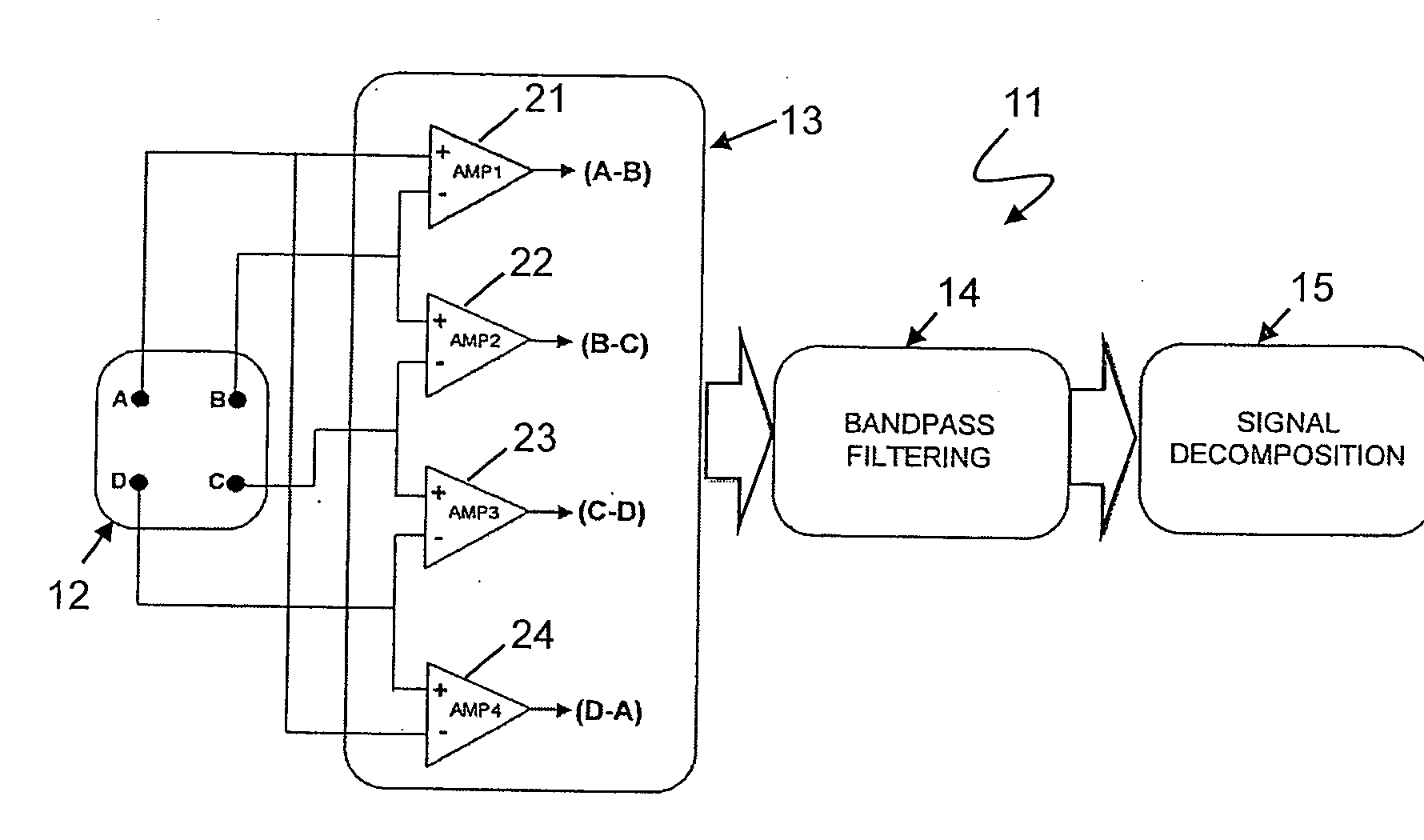
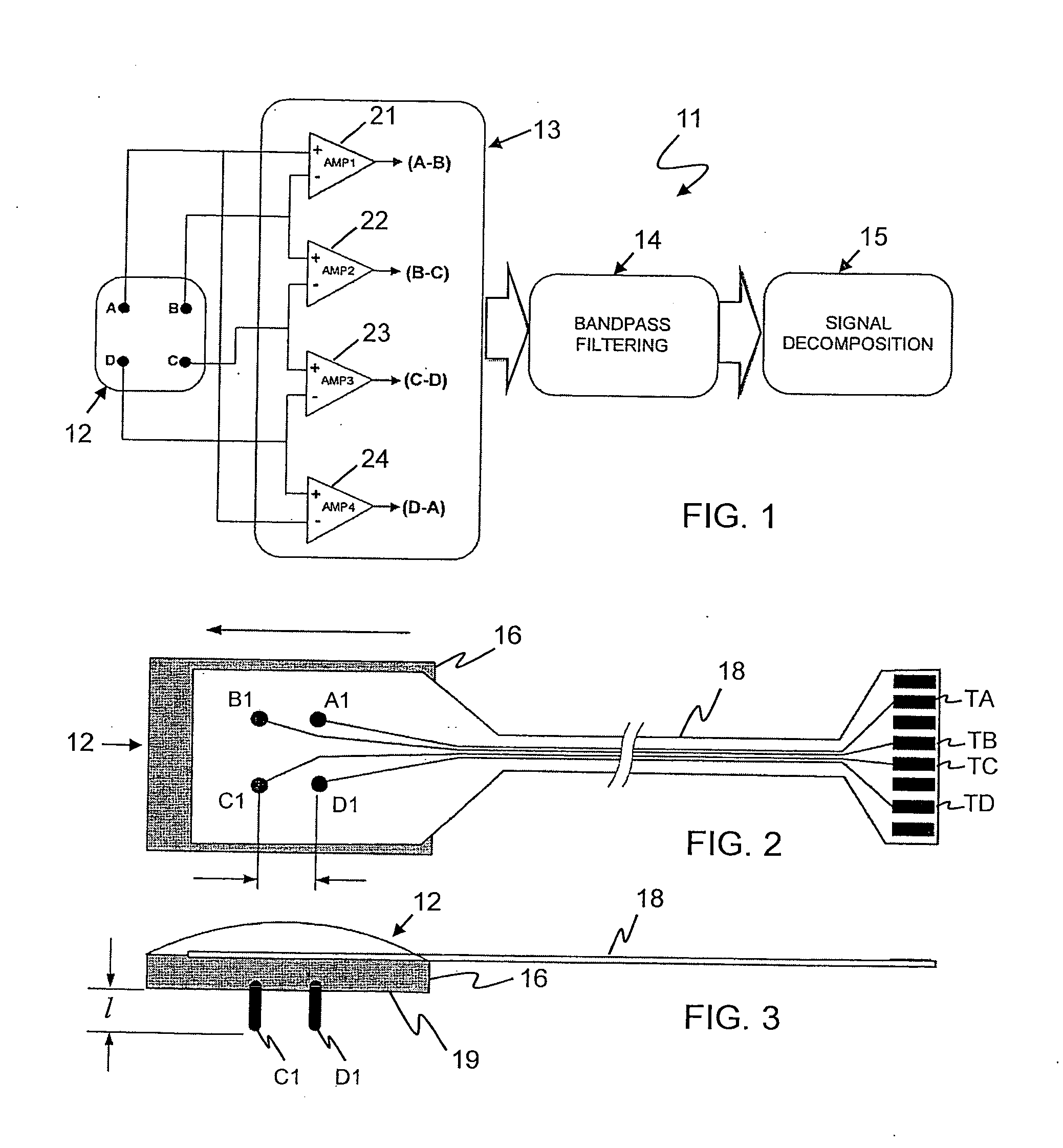
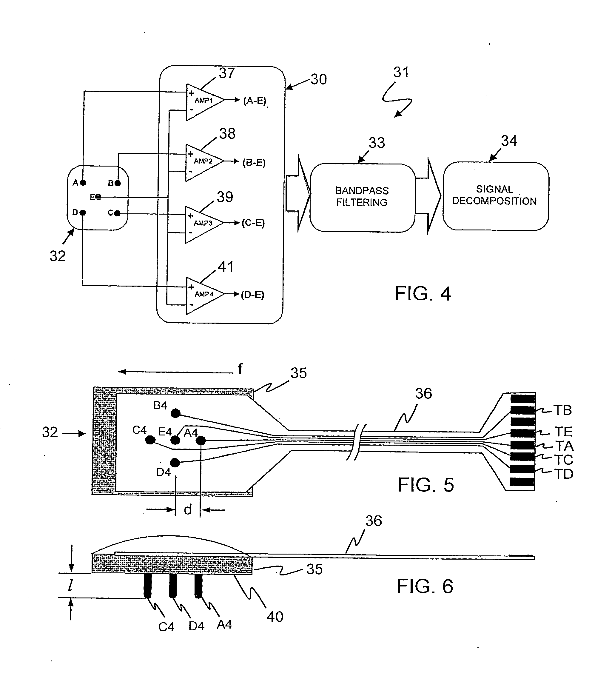
[0034]FIG. 4 depicts another sensor system 31 in which another electrode section embodiment 32 is connected to an amplifier section 30, a filtering section 33 and a decomposing section 34. Included in the section 32 is an electrode array (FIG. 5) composed of electrodes A4, B4, C4, D4 and E4 spaced apart on a rectangular substrate 35. Connected by a cable 36 to the electrodes A4-E4 are, respectively, output terminals TA, TB, TC, TD and TE. As shown in FIG. 6, the electrodes are pins having rounded ends and projecting a length of 2 mm from a bottom surface 35 of the substrate 33. The terminals TA-TE are connected to the amplifier section 30 a section 13 with terminals TA and TE connected to a differential amplifier 37, terminals TB and TE connected to a differential amplifier 38, terminals TC and TE connected to a differential amplifier 39 and terminals TD and TE connected to a differential amplifier 41. Preferably, the electrode pins A4-D4 are uniformly spaced from the electrode pin...

embodiment 52

[0035]FIG. 7 illustrates another sensor system 51 in which an electrode section embodiment 52 is connected to an amplifier section 50, a filtering section 53, and a decomposing section 54. Included in the section 52 is an electrode array (FIG. 8) composed of electrodes A7, B7, C7, D7, E7 and F7 spaced apart on a rectangular substrate 55. Connected by a cable 56 to the electrodes A4-F7 are, respectively, output terminals TA, TB, TC, TD, TE and TF. As shown in FIG. 6, the electrodes are pins having rounded ends and projecting a length of 2 mm from a bottom surface 60 of the substrate 33. The terminals TA-TF are connected to amplifier section 50 with terminals TA and TB connected to a differential amplifier 57, terminals TB and TC connected to a differential amplifier 58, terminals TF and TE connected to a differential amplifier 59 and terminals TD and TE connected to a differential amplifier 61. Preferably, the electrode pin pairs A7 and B7, B7 and C7, E7 and F7, and D7 and E7 are un...


PUM


Abstract

A sensor system for detecting and processing EMG signals including a substrate having a bottom surface adapted for attachment to skin; a plurality of spaced apart electrode arrays projecting from the bottom surface so as to engage the skin and detect EMG signals in muscles located under the substrate; and four differential amplifiers connected to receive EMG signals from four distinct pairs of electrode arrays. The electrode arrays detect the action potentials of the muscle fibers from various orientations so that the shape of an action potential appears substantially dissimilar in each of the four differential pairs.

Description

[0001]This application claims priority from U.S. Provisional Application Ser. No. 60 / 610,435 filed Sep. 16, 2004 entitled SURFACE ELECTRODE FOR SELECTIVE SURFACE EMG SIGNALS.BACKGROUND OF THE INVENTION[0002]Medical discipline employs armament for diagnostics, quantitative objective techniques and tests to evaluate degrees of insult or dysfunction. The object of this invention is to utilize such techniques in the field of motor disorders. Each year approximately one million Americans are struck with a debilitating motor disorder or are afflicted with a disease which impairs their ability to move, carry out normal activities of daily living, and in various ways degrade their quality of life. The most common disorders among these are Stroke, Spinal Cord Injuries, Head Injuries, Parkinson's Disease, Multiple Sclerosis, and various forms of paralysis, such as facial palsy. Although neural lesions associated with upper motoneuron disorders can be imaged with MRI and fMRI magnets to indica...

Claims


Application Information

Patent Timeline
Patent Type & Authority Applications(United States)
IPC IPC(8): A61B5/0488
CPCA61B5/0492A61B5/4082A61B5/296
Inventor DELUCA, CARLO J.GILMORE, L. DONALD
Owner DELUCA CARLO J
Learn More