
Auto-returning assembly with mechanical damper

a technology of mechanical damper and auto-returning assembly, which is applied in the direction of drawers, furniture parts, domestic applications, etc., can solve the problems of hazard to people walking past, damage to furniture, damage to drawers, and any fragile contents

Inactive Publication Date: 2009-02-05
CHUNG CHIN HSIANG
View PDF6 Cites 44 Cited by
  • Summary
  • Abstract
  • Description
  • Claims
  • Application Information

AI Technical Summary

Benefits of technology

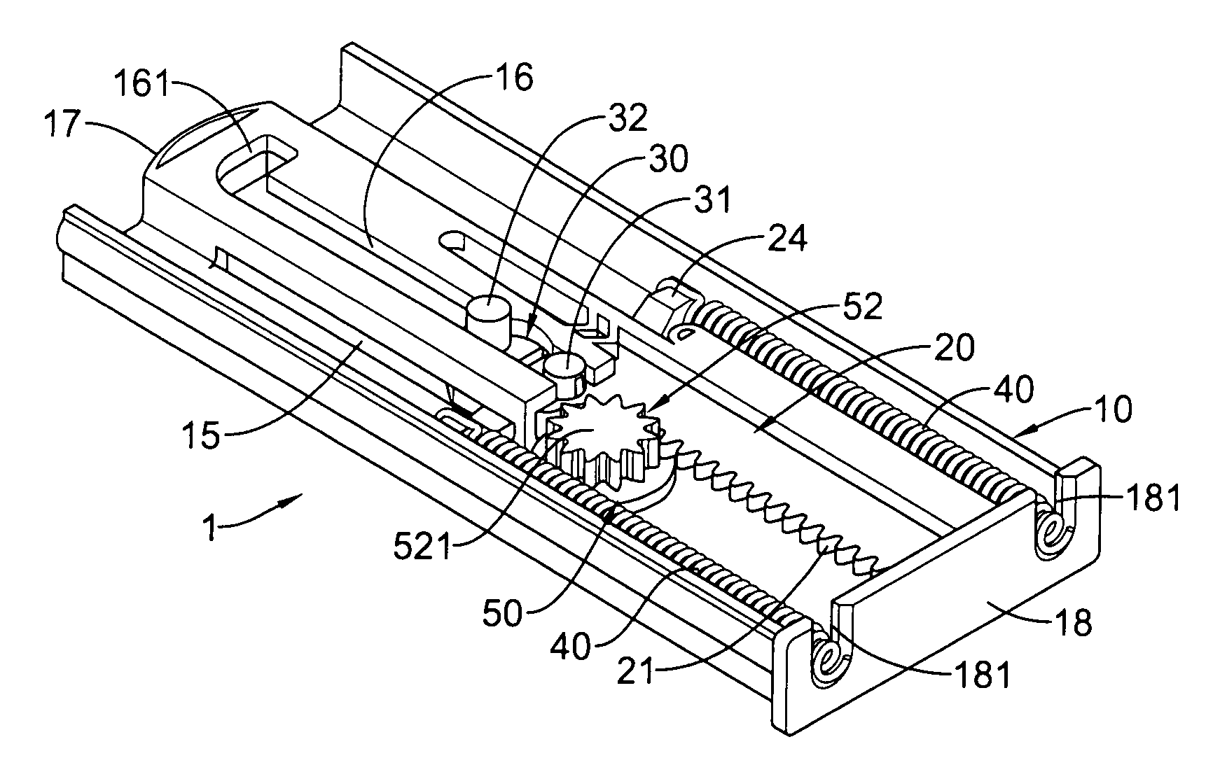
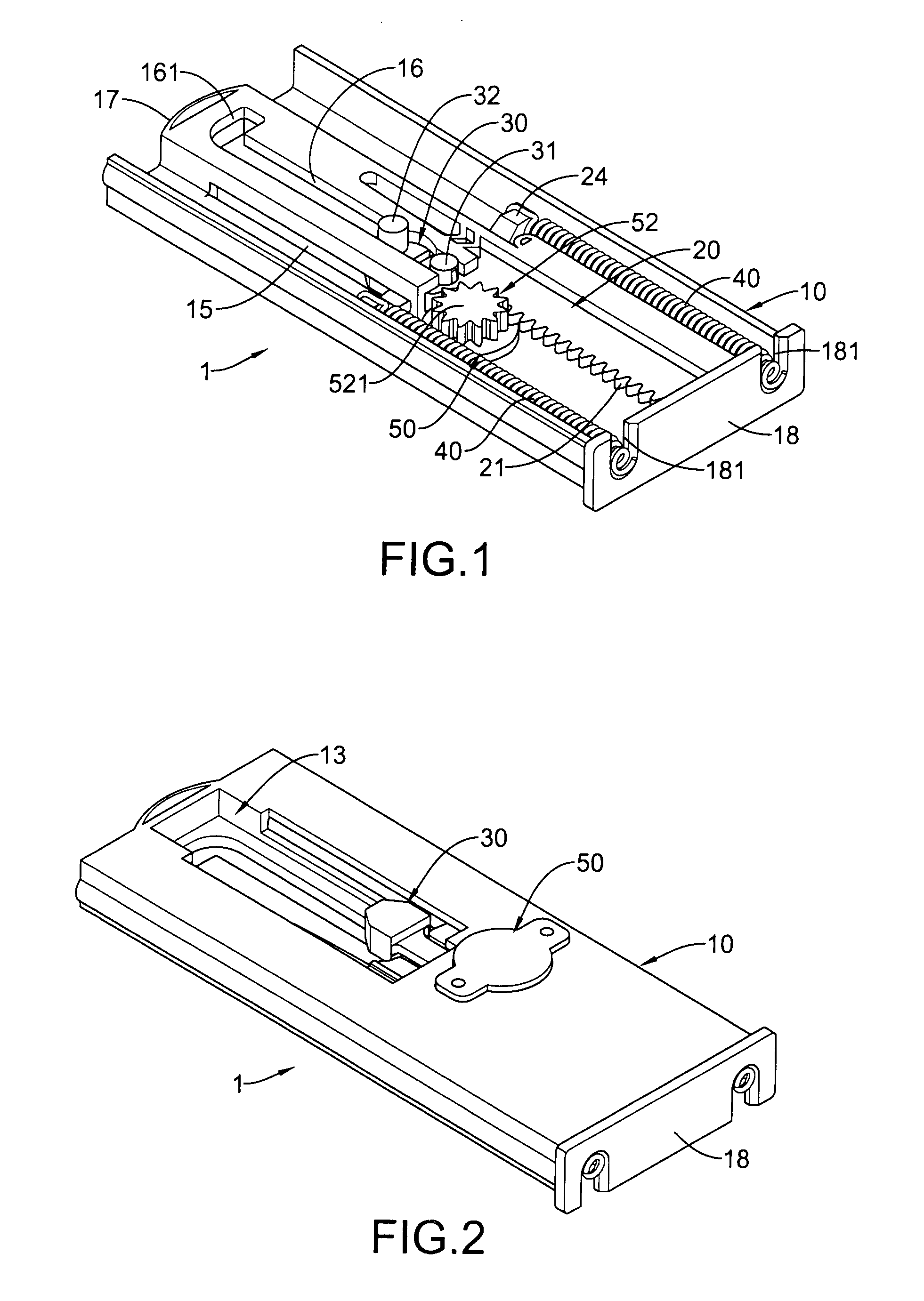
[0014]The main objective of the present invention is to provide an auto-returning assembly with mechanical damper for used in conjunction with a drawer rail that can provide a buffering effect when the drawer rail is returning.
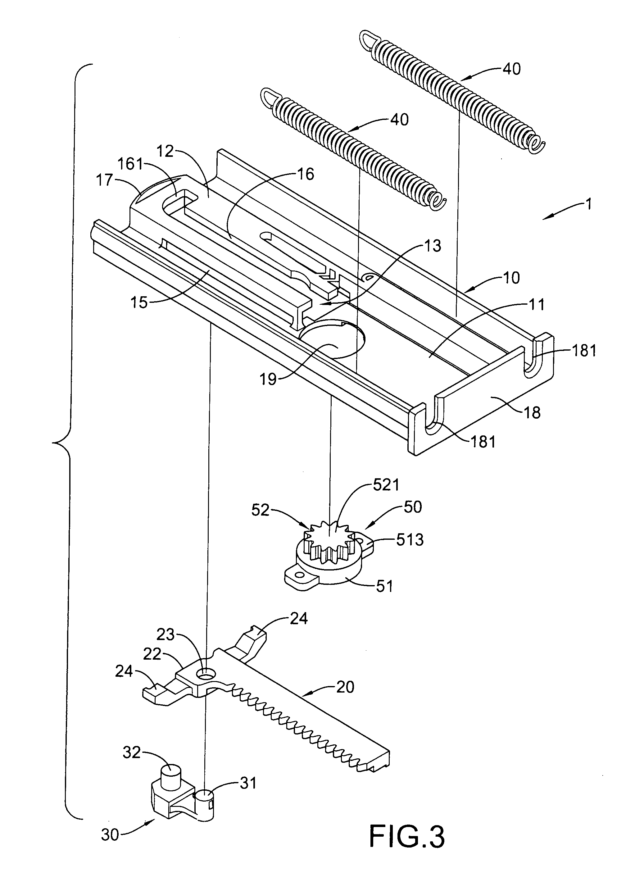
[0015]The auto-returning assembly is used on drawer rail and has a body, a rack, a locking protrusion, at least one spring and a damper. The body has a base and a guiding mount. The guiding mount is formed on the base and has a guide slot. The rack is mounted slidably on the body. The locking protrusion is mounted rotatably on the rack and slidably in the guiding slot and has a pivoting protrusion and a locking protrusion. The at least one spring is connected to the body and the rack. The damper is connected securely to the body and engages the rack and has a casing and a buffering wheel. Wherein, the resistance medium provides a damping effect to the buffering wheel when the buffering wheel rotates in a direction. When the spring pulls the drawer rails back, rack forces the damper wheel to turn that encounters high resistance and slows the movement of the drawer rail by the resistance medium.

Problems solved by technology

However, when full, the drawer becomes heavy so drawer rails are mounted between the drawer and the furniture.
Furthermore, when drawers are not returned into the furniture they may cause a hazard to people walking past or, especially when filled with heavy items, may break.
However, the spring (64) provides a strong force to pull the drawer back into the furniture, causing the drawer to knock against the furniture, damaging the furniture, drawer and any fragile contents.

Method used


Image

  • Auto-returning assembly with mechanical damper
  • Auto-returning assembly with mechanical damper
  • Auto-returning assembly with mechanical damper

Examples


Embodiment Construction

[0026]With reference to FIGS. 1 to 4, an auto-returning assembly with mechanical damper (1) in accordance with the present invention comprises a body (10), a rack (20), a locking protrusion (30), at least one springs (40) and a damper (50).

[0027]The body (10) may be a container and has a base (11), a guiding mount (12), an optional protecting bar (17), an optional connecting panel (18) and an optional damper mount (19).

[0028]The base (11) has a front end, a rear end and a recess. The recess is defined in the base (1) between the front end and the rear end. The guiding mount (12) is formed on and protrudes from the base (11) near the front end and has a front end, a rear end, two sidewalls, a top face, an opening (13), two optional channels (15) and a guide slot (16). The opening (13) is formed in rear end of the guiding mount (12). The channels (15) are respectively formed through the sidewalls of the guiding mount (12). The guide slot (16) is formed through the top face of the guid...


PUM


Abstract

An auto-returning assembly with mechanical damper is used in conjunction with a drawer rail and has a body, a rack, a locking protrusion, at least one spring and a damper. The body has a base and a guiding mount. The guiding mount is formed on the base and has a guide slot. The rack is mounted slidably on the body. The locking protrusion is mounted rotatably on the rack and slidably in the guiding slot and has a pivoting protrusion and a locking post. The at least one spring is connected to the body and the rack. The damper is connected securely to the body and engages the rack and has a casing and a buffering wheel. When the spring pulls the drawer rails back, rack forces the damper wheel to turn that encounters high resistance and slows the movement of the drawer rail.

Description

BACKGROUND OF THE INVENTION[0001]1. Field of the Invention[0002]The present invention relates to an auto-returning assembly for a drawer rail, and more particularly relates to an auto-returning assembly that can provide a damper effect when the drawer rail is returning.[0003]2. Description of Related Art[0004]A drawer is mounted in a variety of furniture and slides into or out of the furniture for storage. However, when full, the drawer becomes heavy so drawer rails are mounted between the drawer and the furniture.[0005]Furthermore, when drawers are not returned into the furniture they may cause a hazard to people walking past or, especially when filled with heavy items, may break.[0006]Therefore, to further ease closing the drawer and improve safety, an auto-returning device is mounted on the drawer rail to provide an auto-returning function to the drawer.[0007]With reference to FIG. 8, a conventional drawer rail (2) has a stationary bracket (3), a stationary track (4) and an inner...

Claims


Application Information

Patent Timeline
IPC IPC(8): A47B88/12
CPCA47B2210/0094A47B88/047A47B88/467
Inventor CHUNG, CHIN-HSIANG
Owner CHUNG CHIN HSIANG
Learn More