
Pneumatic Tire

Active Publication Date: 2009-02-05
BRIDGESTONE CORP +1
View PDF6 Cites 54 Cited by
  • Summary
  • Abstract
  • Description
  • Claims
  • Application Information

AI Technical Summary

Benefits of technology

[0005]It therefore is an object of the present invention to provide a pneumatic tire with a still enhanced durability by efficient temperature reduction at a portion where deteriorations tend to occur in a variety of pneumatic tires.
[0006]For solution of the objective described, the present inventor has committed studies in view of a tire surface deformable for enhancement in efficiency of heat dissipation, finding that the efficiency of heat dissipation can be still enhanced by provision of a tire-outer lateral side or tire-inner lateral side with tire-radially arranged grooves or ribs defined in shape.
[0008]In respect of the invention, a tire side portion with a tendency for a failure to occur is provided with a turbulent generating concavo-convex part, thereby allowing heat dissipation of the tire side portion to be promoted with turbulent flows of air generated at the turbulent generating concavo-convex part. The tire is made of a rubber material with a bad heat conductivity, and for the heat dissipation, a greater effect is expectable by promoting turbulent generation to have turbulent air flows directly hitting the tire side portion, than having an expanded radiation area for heat dissipation to be promoted.
[0018]In addition, the turbulent generating concavo-convex part may be divided to be discontinuous in the extending direction. Further, the turbulent generating concavo-convex part may be unevenly arranged along a tire-circumferential direction. In this connection, for the ribs provided on a surface of the tire side portion, there accrue stagnant regions behind influent air, worsening heat dissipation in part in comparison with the case of no provision of ribs. In order for elimination of such parts as worsened of heat dissipation to enhance the heat transfer in average, it may be effective for the turbulent generating concavo-convex part to be divided so as to be discontinuous in the extending direction.
[0019]Yet more, according to the invention, among others, a heavy-load-oriented tire, and a run flat tire provided with reinforcing rubber crescents at a tire side portion may have reduced temperatures at their tire side portions.

Problems solved by technology

The pneumatic tire may have raised temperatures accompanied by, among others, promotion of temporal variations such as changes in property of materials, or causation to a break or such in a high-speed running, which is unfavorable from a viewpoint of durability.

Method used


Image

  • Pneumatic Tire
  • Pneumatic Tire
  • Pneumatic Tire

Examples


first embodiment

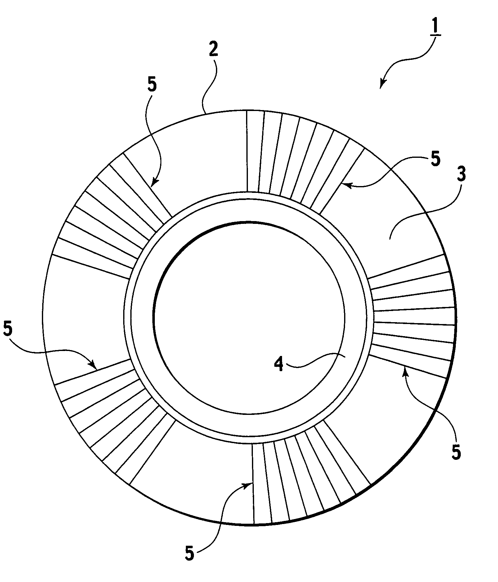
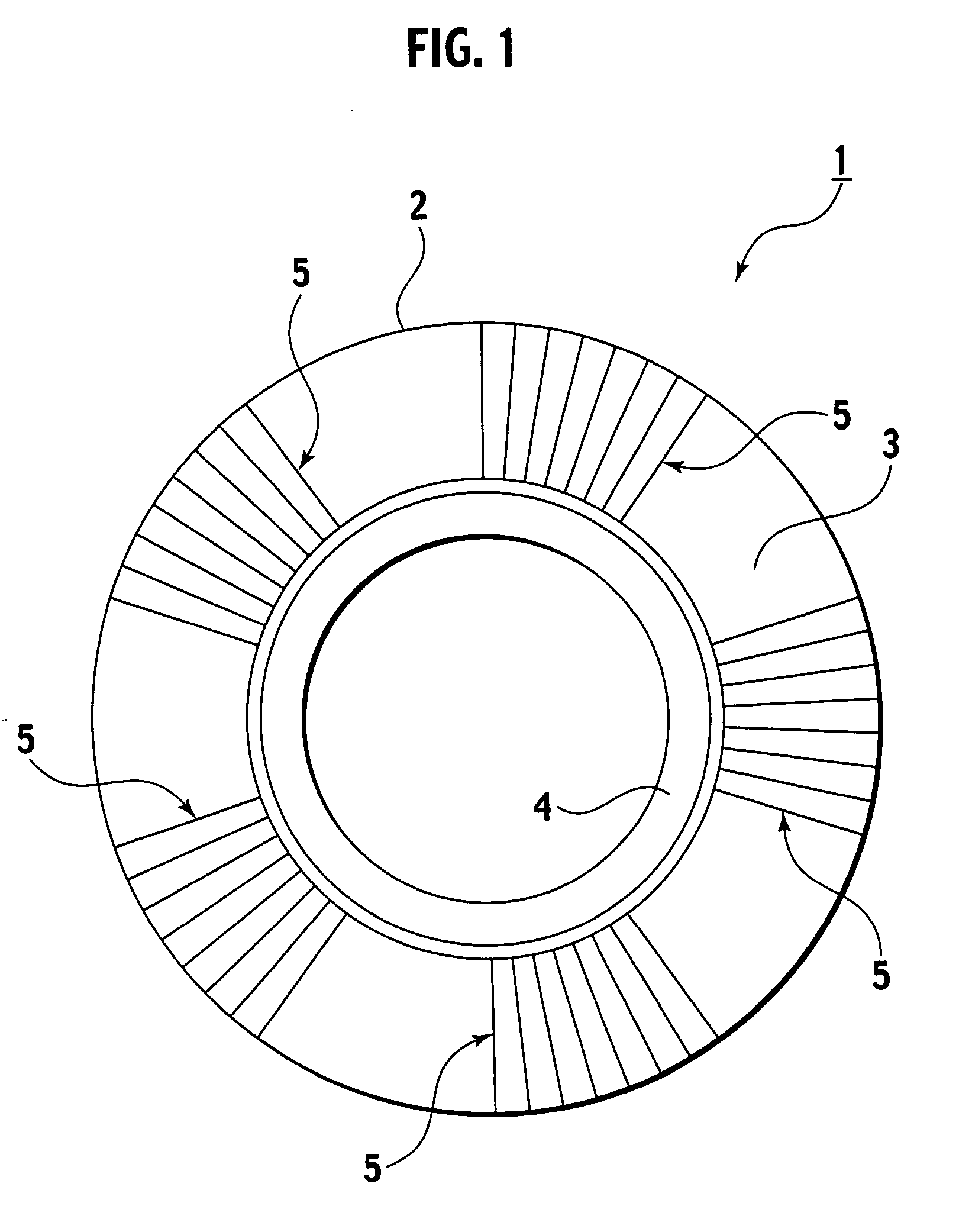
[0054]FIG. 1 to FIG. 3 show a run flat tire 1 as a pneumatic tire according to a first embodiment of the present invention, and FIG. 4 to FIG. 6 show a turbulent generating concavo-convex part 5 provided to a tire side portion 3 of the run flat tire 1. FIG. 1 is a side view of the run flat tire 1; FIG. 2, a perspective view of an essential portion of the run flat tire 1; FIG. 3, a sectional view, as a radial section, of the essential portion of the run flat tire 1; FIG. 4, a perspective view of an essential portion of the turbulent generating concavo-convex part 5; FIG. 5, a sectional view of the turbulent generating concavo-convex part 5; and FIG. 6, a side view of a rib of the turbulent generating concavo-convex part 5 seen in a tire-circumferential direction.

[0055]

[0056]As shown in FIG. 1 to FIG. 3, the run flat tire 1 is made up by a tread portion 2 to be brought into contact with a road surface, tire side portions 3 at both sides of the tire, and bead portions 4 provided along ...

second embodiment

[0075]FIG. 8 and FIG. 9 show a run flat tire 1D as a pneumatic tire according to a second embodiment of the present invention. FIG. 8 is a perspective view of the run flat tire 1D; FIG. 9(a), a side view of a plurality of ribs 20 of turbulent generating concavo-convex parts provided to a tire side portion 3; FIG. 9(b), a side view of a tire-radially inner end (at the side of an axis of revolution of the tire) of a rib seen from the tire revolution axis side; FIG. 9(c), a section A-A of FIG. 9(a); and FIG. 9(d), a side view of the run flat tire. It is noted that, for the run flat tire 1D according to the present embodiment, like parts to the run flat tire 1 according to the first embodiment are designated by like reference characters, to eliminate redundancy.

[0076]For the run flat tire 1D in the present embodiment, the general configuration is like to the first embodiment described, and is made up by a tread portion 2 to be brought into contact with a road surface, tire side portions...


PUM


Abstract

To provide a pneumatic tire having a tire side portion with an enhanced durability according to the present invention, a run flat tire (1) has a turbulent generating concavo-convex part (5) composed of grooves and ribs and extending along at least part of a tire side portion, and a pattern is set to the turbulent generating concavo-convex part (5), in which for the turbulent generating concavo-convex part (5), letting h be a height, p be a pitch, and w be a width, a relationship is met such that 1.0≦p / h≦50.0, and 1.0≦(p−w) / w≦100.0.

Description

TECHNICAL FIELD[0001]The present invention relates to a pneumatic tire, and particularly, to a pneumatic tire adapted for reduction of temperatures at a tire side portion where deteriorations tend to develop.BACKGROUND ART[0002]The pneumatic tire may have raised temperatures accompanied by, among others, promotion of temporal variations such as changes in property of materials, or causation to a break or such in a high-speed running, which is unfavorable from a viewpoint of durability. In particular, for a truck bus radial (TBR) tire or off-road radial (ORR) tire to be heavy-loaded in use, or for a run flat tire in a flat run (running with an internal pressure of 0 kPa), the reduction of tire temperature has been a significant desideratum for enhancement of durability. For example, a run flat tire has reinforcing rubber crescents, which become very hot with concentrated radial deformations in a flat run, giving a significant influence on durability.[0003]In a known relevant art for ...

Claims


Application Information

Patent Timeline
IPC IPC(8): B60C13/02B60C17/00
CPCB60C13/02
Inventor YAMAGUCHI, MASASHI
Owner BRIDGESTONE CORP
Learn More