Combustion engine and electric generator
- Summary
- Abstract
- Description
- Claims
- Application Information
AI Technical Summary
Benefits of technology
Problems solved by technology
Method used
Image

Examples
Embodiment Construction
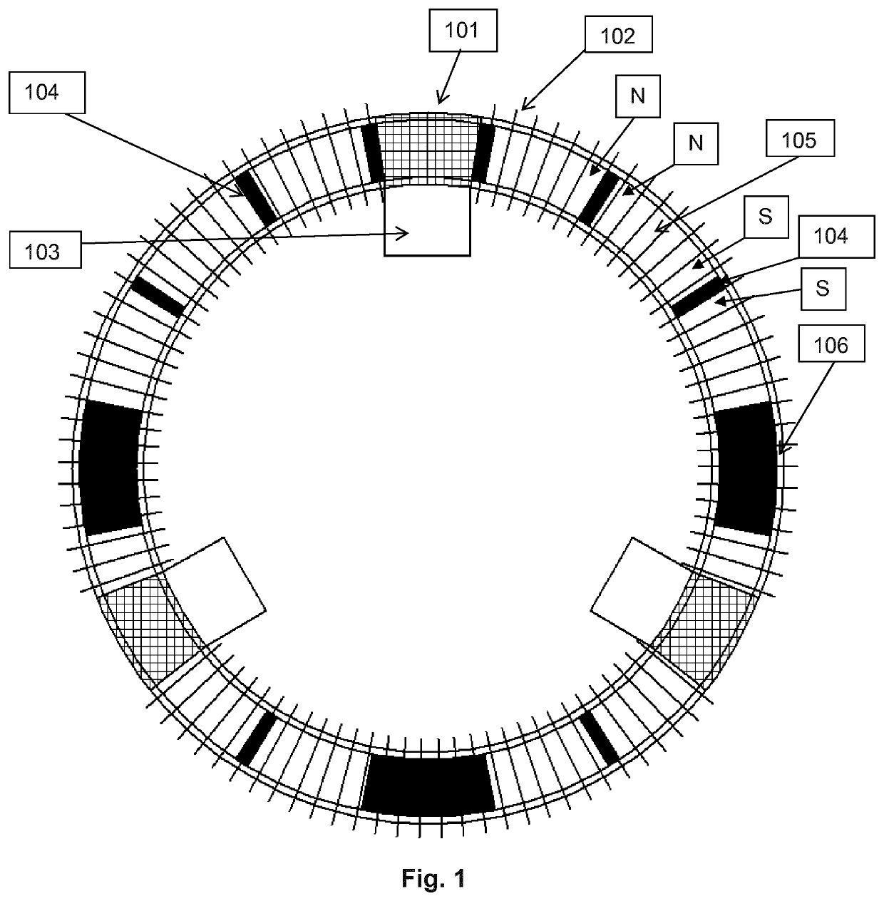
[0039]FIG. 1 depicts the concept of the engine as an inner ring of permanent magnets with steel interface sections, that are forced to rotate through a ring of coil windings in order to generate an electrical current.
[0040]The combustion system 103 is located internally of the ring of magnets 105, another embodiment may have the combustion system 103 external to the ring of magnets 105 as a potentially more effective interface with the steel combustion interface sections 106.
[0041]FIG. 1 shows an embodiment of the combustion engine where the combustion systems 103 are internal to the ring of coil windings 102 but in other embodiments may provide a more effective transfer of mechanical energy due to the curvature of the steel combustion interface section 106 if the combustion systems were external to the ring of coil windings.
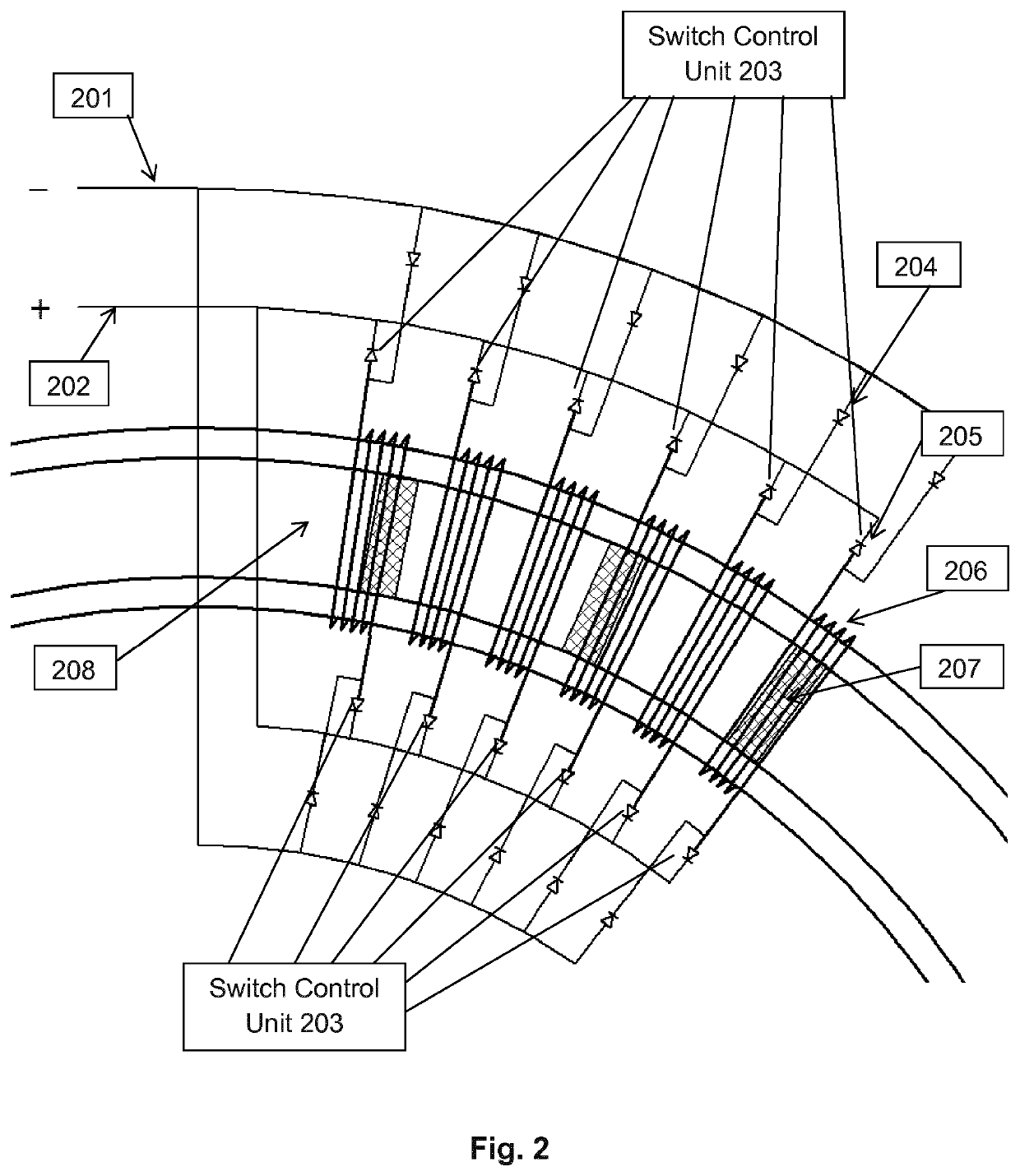
[0042]The Combustion Engine Generator is designed to generate an electrical current in the coil windings 102, detailed further below in FIG. 2, through the rota...
PUM
 Abstract
Description
Claims
Application Information
 - R&D
- Intellectual Property
- Life Sciences
- Materials
- Tech Scout
- Unparalleled Data Quality
- Higher Quality Content
- 60% Fewer Hallucinations
Browse by: Latest US Patents, China's latest patents, Technical Efficacy Thesaurus, Application Domain, Technology Topic, Popular Technical Reports.
© 2025 PatSnap. All rights reserved.Legal|Privacy policy|Modern Slavery Act Transparency Statement|Sitemap|About US| Contact US: help@patsnap.com