
Height-Adjustable Molding Device for Molding Thermoplastic Recipients of Various Heights

Active Publication Date: 2009-01-29
SIDEL PARTICIPATIONS SAS
View PDF7 Cites 16 Cited by
  • Summary
  • Abstract
  • Description
  • Claims
  • Application Information

AI Technical Summary

Benefits of technology

[0012]It is an essential object of the invention to propose an improved technical solution that is more economical both in terms of material and in terms of machining time but which does, however, preserve the freedom to adapt the useful height of the shells to suit the actual height of the containers that are to be manufactured.
[0016]By virtue of these arrangements, the two shell holders still have a radial support in those parts thereof that are not cooperating with the respective shells, but at the same time, the shells themselves can therefore be manufactured with a shorter height in relation to the actual height of the containers that are to be manufactured.
[0021]A second exemplary embodiment, which is, in practice, preferred on account of the simplicity with which the constituent parts can be manufactured, is for the reinforcing means to comprise two semi-tubular portions which are situated on the respective shell holders at the positions left unoccupied by the shorter shell holders; these two semi-tubular portions have a height substantially equal to the difference in respective heights of the shell holders and the shells and their respective longitudinal frontal surfaces bear against one another just as do the shells, when the mold is in the closed position. In the aforementioned preferred embodiment, the semi-tubular portions are positioned in the lower parts of the respective shell holders. Advantageously, the semi-tubular portions are mechanically secured to the respective shells in such a way as to form one-piece entities that are quicker and easier to fit or to remove and, to these ends, provision is made for the semi-tubular portions to have, passing through their wall, longitudinal bores able to accept members for screwing them to the respective shells. In the context of this preferred arrangement, the semi-tubular portions may be manufactured economically from portions of tube of suitable diameter and thickness, with a smaller amount of machining and without loss of material.

Problems solved by technology

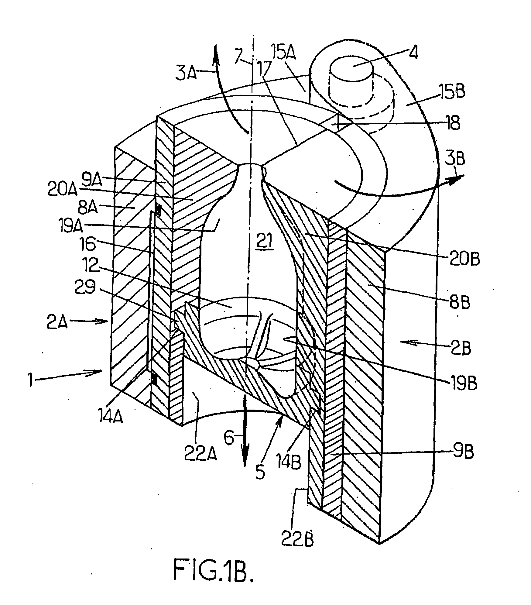
However, this known structure does at the same time have the appreciable disadvantage that the shells 20A, 20B are machined from solid, which, when machining the lower parts 22A, 22B, entails removing a significant volume of material.
This results in waste materials, machining time, and therefore results in height costs.

Method used


Image

  • Height-Adjustable Molding Device for Molding Thermoplastic Recipients of Various Heights
  • Height-Adjustable Molding Device for Molding Thermoplastic Recipients of Various Heights
  • Height-Adjustable Molding Device for Molding Thermoplastic Recipients of Various Heights

Examples


Embodiment Construction

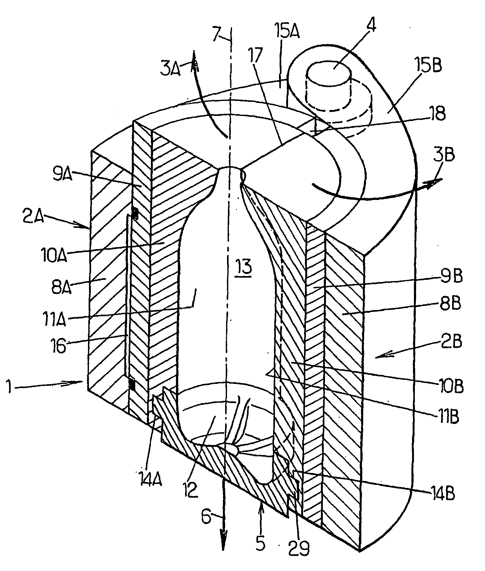
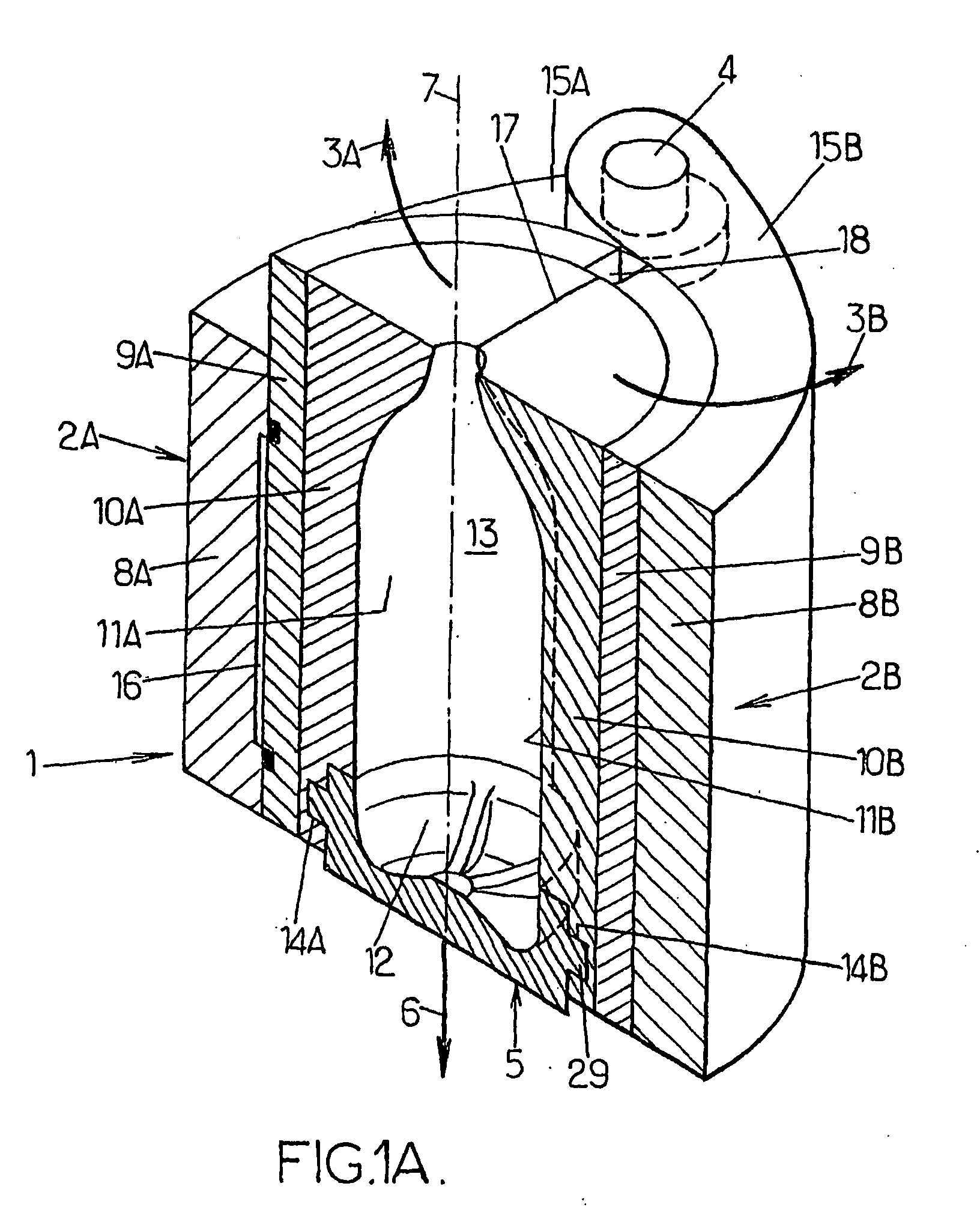
[0029]In the remainder of the description, the same numerical references as were used in FIG. 1B will be kept for denoting parts that are similar.

[0030]According to the invention, the following combination of arrangements is provided:[0031]to manufacture containers of the tallest height (maximum height), the shell holders 9A, 9B and shells 10A, 10B have substantially identical respective heights, as shown in FIG. 1A;[0032]to manufacture containers of heights shorter than said maximum height, the shells 20A, 20B have a height shorter than that of the respective shell holders 9A, 9B, as visible in FIGS. 2A, 2C and 3A, and reinforcing means are provided on the respective internal faces of the shell holders 9A, 9B in those parts 30A, 30B thereof that are not cooperating with the respective shells 20A, 20B, said reinforcing means being able radially to reinforce those parts 30A, 30B of the shell holders that are not cooperating with the respective shells 20A, 20B when the pressure-compen...


PUM

PropertyMeasurementUnit
Pressureaaaaaaaaaa
Shapeaaaaaaaaaa
Heightaaaaaaaaaa

Abstract

The invention relates to a moulding device for blowing thermoplastic recipients of various heights, said device comprising a mould provided with two mould halves and a mould bottom which are mutually mobile. Each mould half comprises a mould carrier, a chill carrier and a chill, said two chills and the mould bottom comprising mould impressions, which together define a moulding cavity. The inventive device also comprises means for compensating the blowing pressure, said means being provided between a mould carrier and the associated chill carrier. For recipients with the maximum height, the chill carriers and chills are the same height. For lower recipients, the chills are lower than the chill carriers and radially reinforcing means are provided on the internal faces of the carriers in the parts thereof which do not co-operate with the chills.

Description

FIELD OF THE INVENTION[0001]The present invention relates in general to the field of molding devices for manufacturing containers, particularly bottles, made of thermoplastic, such as PET, by blow-molding or stretch-blow-molding and it relates more particularly to improvements made to those of these molding devices that are designed to manufacture such containers, particularly such bottles, which are liable to have different heights, said molding devices comprising at least one mold which comprises two mold halves able to move relative to one another, for example in rotation about a fixed common axle, and a mold base able to move relative to the two mold halves in axial translation, each mold half comprising a mold holder, a shell holder fixed to the mold holder and a shell supported by the shell holder, the two shells and the mold base comprising respective molding cavity portions which, when the mold is in the closed position, together define a molding cavity, means for compensati...

Claims


Application Information

Patent Timeline
IPC IPC(8): B29C49/30
CPCB29C33/26B29C49/12B29K2067/00B29C2049/4858B29C2049/4892B29C49/48B29C2049/7831
Inventor DANNEBEY, LAURENTCANCHEL, ERICPITTE, PHILIPPE
Owner SIDEL PARTICIPATIONS SAS
Learn More