
Multi-channel laser interferometric method and apparatus for detection of ultrasonic motion from a surface

a laser interferometer and surface technology, applied in response signal detection, instruments, measurement devices, etc., can solve the problems of reducing interference efficiency, sensitivity not directly improved, and very low sensitivity of the interferometer on rough surfaces

Active Publication Date: 2009-01-29
SOUND & BRIGHT
View PDF16 Cites 19 Cited by
  • Summary
  • Abstract
  • Description
  • Claims
  • Application Information

AI Technical Summary

Problems solved by technology

Single speckle selection means that the collecting aperture is very small and thus these interferometers have very low sensitivity on rough surfaces.
Instead of single speckle detection, these interferometers can be optimized for collecting few speckles in order to increase the amount of collected light, but unfortunately the sensitivity is not directly improved by the higher amount of collected light because the random phase distribution of speckles reduces the interference efficiency.
In most industrial application, the positioning of the sample is not controlled accurately.
An optical system with high sensitivity but high requirement for target positioning will lead to an overall system with poor sensitivity, where good signals are acquired only sporadically when the sample moves through the optimum position.
To better control the sample position may not be easily possible or may highly increase the overall cost of the inspection system, making the system not affordable and limiting its field of application.

Method used


Image

  • Multi-channel laser interferometric method and apparatus for detection of ultrasonic motion from a surface
  • Multi-channel laser interferometric method and apparatus for detection of ultrasonic motion from a surface
  • Multi-channel laser interferometric method and apparatus for detection of ultrasonic motion from a surface

Examples


first embodiment

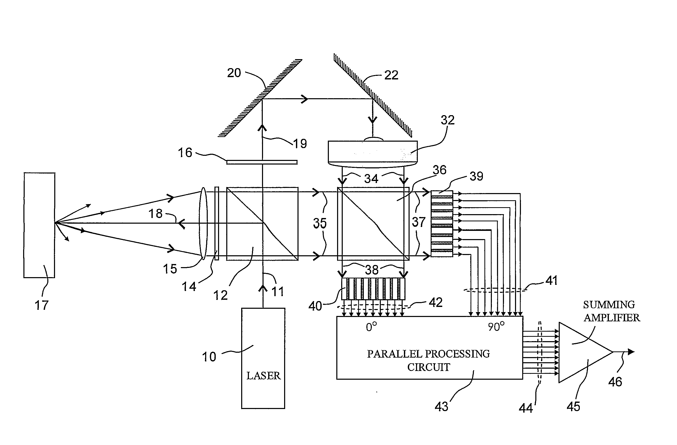
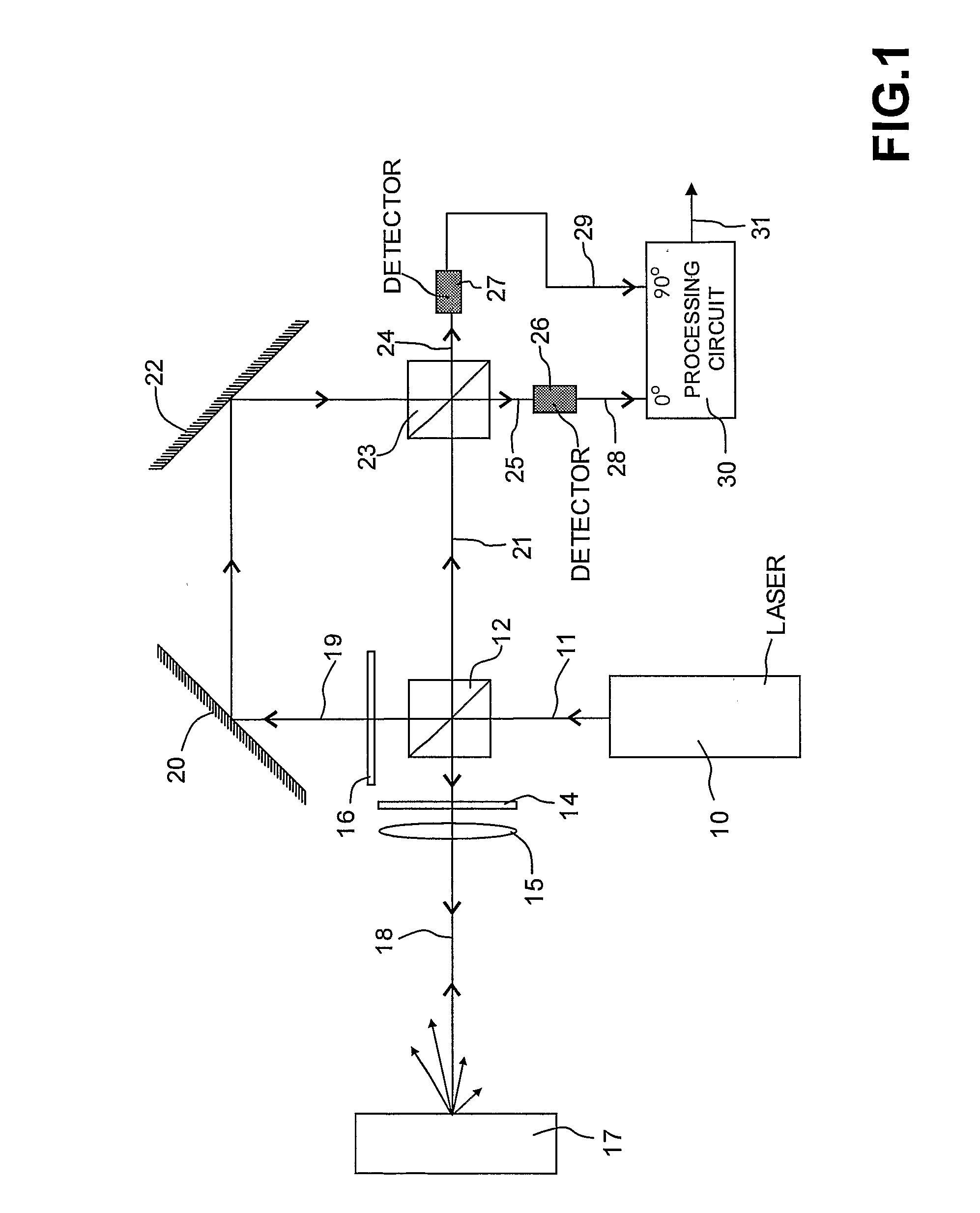
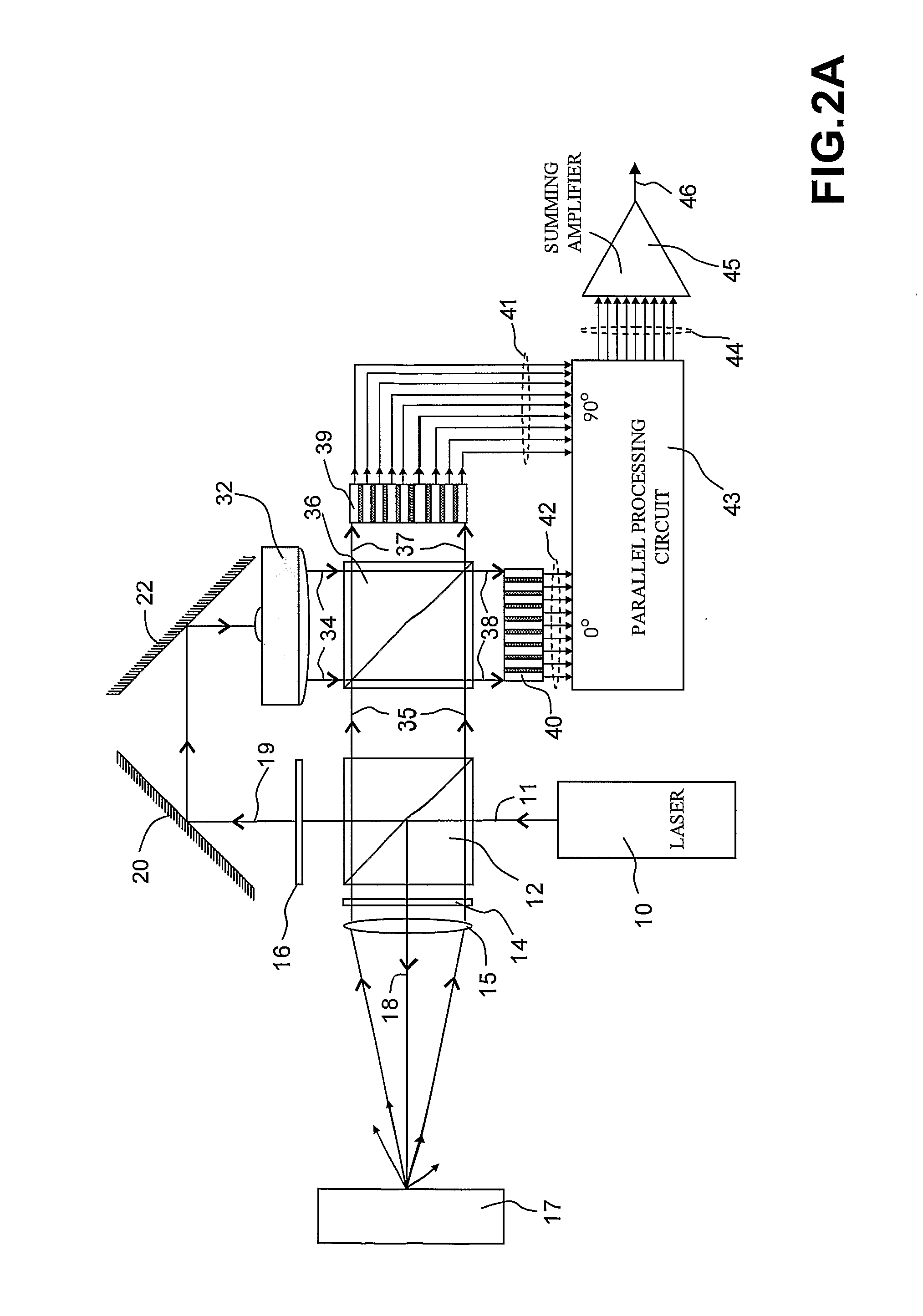
[0058]FIG. 2B illustrates a variant of the first embodiment shown in FIG. 2A which includes a differential detection scheme. The reference beam 19 passes through a half wave plate 48 whereby reference beam is linearly polarized and orthogonal to the object beam polarization 35. In this embodiment, the object beam 35 and the crossed polarized reference beam 47 are first divided by dividing means, as a beam splitter 49, into two optical signals 50 and 51. One of the optical signals, the optical signal 50 in FIG. 2B, passes through a quarter wave plate 52 which has its optical axis oriented along the polarization axis of the optical signal 50, resulting in a 90° phase shift between the two orthogonal polarizations. In this embodiment, the combining means comprise two polarizing beam splitters 53a and 53b and the receiving means comprise four arrays of detectors 56a, 56b, 57a and 57b. The partially transmitted object beam and reference beam 50 and 51 are made to interfere along the two ...

second embodiment

[0059]FIG. 3 illustrates a second embodiment according to the invention, in which the quadrature detection scheme is replaced by an heterodyne detection scheme. Similarly to FIG. 2, the laser beam 11 is split in a probe beam 18 and a reference beam 67. A frequency shifting device 68, such as a Bragg cell, is driven by a single frequency oscillator 66 producing a frequency shift at fB of the reference beam 67. After frequency shifting, the reference beam is expanded by the beam expander 32 such as to fully fill the active area of the array of detector 71. The linearly polarized object beam 35 and the linearly polarized frequency shifted reference beam 67 are mixed by the beam splitter 69 and the heterodyne optical fringe signal 70 is detected by the array of detector 71. The heterodyne signals 72 are processed by a parallel processing circuitry 75. The multiple processed signals 76 are then summed by a summing amplifier 45 in order to give an average output signal 78 proportional to ...

third embodiment

[0061]FIG. 4B illustrates a first variant of the third embodiment shown FIG. 4A which includes two arrays of detectors 82 and 88, making use of all the light available. Similarly to FIG. 4B, The linearly polarized object beam 35 and the linearly polarized reference beam 79 are mixed by the beam splitter 80. The optical fringe signals 81 and 87 are detected by the array of detectors 82 and 88. The signals 83 and 89 are processed by a parallel processing circuitry 90. In this embodiment the number of signals is doubled compared to the previous embodiment shown FIG. 4A. Similarly to the previous embodiment shown FIG. 4A, the parallel processing circuitry 90 process each signal independently and it can be based on either the square demodulation, as explained below in reference to FIG. 9A, or the rectification demodulation, as explained below in reference to FIG. 9B. Because each signal are processed independently, there is no accuracy requirement regarding the relative positioning of th...


PUM

PropertyMeasurementUnit
displacementaaaaaaaaaa
opticalaaaaaaaaaa
phase shiftaaaaaaaaaa

Abstract

A multi-channel laser interferometric method and apparatus are provided for optically measuring transient motion from a surface (17). A laser beam (11) is generated and then divided into first and second beams having respective intensities representing minor and major fraction of the predetermined laser intensity. The reference beam (18) illuminates the surface (17) at which deformation is expected. The light back-scattered by the surface is collected by a single aperture lens (15) and then made to interfere with the probe beam (67) which has been expanded (32), onto a two-dimensional array of detectors (71). Each signal (83) corresponding to each detector of the array is converted individually to an electrical signal, each electrical signal is amplified and processed (84), and the plurality of processed signals (85) is then averaged in an electrical summing means (45).

Description

BACKGROUND OF INVENTION [0001]The present invention relates to laser interferometric method and apparatus with large collecting aperture for measuring motion from a surface. The invention is particularly directed toward detecting small displacement of a surface, and more particularly, an optically scattering surface, of a workpiece subjected to ultrasound, where the workpiece does not need to be accurately positioned.[0002]The detection of phase modulation of an optical wave is important for various field of application where optical beams are used to detect the small motion of an object. This is the case of laser detection of ultrasound and transient body motion such as those produced by the sudden absorption of a laser pulse. The technique based on laser generation and detection, known as Laser Ultrasonic (LU) or Laser Based Ultrasonic (LUB), allows for remote and non-contact detection and generation of ultrasound. Laser ultrasonics can thus be advantageously used for inspection ...

Claims


Application Information

Patent Timeline
Patent Type & Authority Applications(United States)
IPC IPC(8): G01B9/02G01N29/24G01N29/42
CPCG01N29/2418G01N29/42G01N2291/0427G01B9/02003G01B9/02081G01B9/02041G01B9/02082G01B9/02032G01B2290/70G01B9/02057
Inventor POUET, BRUNO FRANCOIS
Owner SOUND & BRIGHT
Learn More