Eureka AIR delivers breakthrough ideas for toughest innovation challenges, trusted by R&D personnel around the world.

Integrated ambient light sensor and distance sensor

a technology of ambient light sensor and distance sensor, which is applied in the direction of optical radiation measurement, distance measurement, pulse technique, etc., can solve the problems of increased manufacturing cost and energy saving in order to prolong battery li

Active Publication Date: 2009-01-29
EMINENT ELECTRONICS TECH
View PDF23 Cites 116 Cited by
  • Summary
  • Abstract
  • Description
  • Claims
  • Application Information

AI Technical Summary

Benefits of technology

The present invention provides an integrated sensor that can perform multiple optoelectronic functions including ambient light sensing, proximity sensing, and user presence detection. The sensor is controlled by a silicon-based integrated circuit (“IC”) sensing device, an indicating light-emitting device (“ILD”), and a projecting light-emitting device (“PLD”). The mechanical design of the package prevents light saturation of the LSIC and allows accurate and sustainable light sensing operations. The sensor includes a transparent or semi-transparent structure for containing and housing the device. The invention also provides a method of operating the integrated sensor in at least two modes including an ambient light sensing mode and a proximity sensing mode.

Problems solved by technology

One challenge that arises with the illumination of such displays is the requirement to conserve energy in order to prolong battery life.
In this example, manufacturing costs are increased due to the requirement of a nonlinear surface to define the necessary angles.
Further, the integrated circuit package is not used to sense ambient light conditions.
However, the use of infrared light for ambient light detection does not adequately match visible ambient light seen by the human eye, and therefore, an electronic device that incorporates such a sensor may not provide sufficient illumination to a display so that a user can operate the device in varying ambient light levels.

Method used


Image

  • Integrated ambient light sensor and distance sensor
  • Integrated ambient light sensor and distance sensor
  • Integrated ambient light sensor and distance sensor

Examples


Embodiment Construction

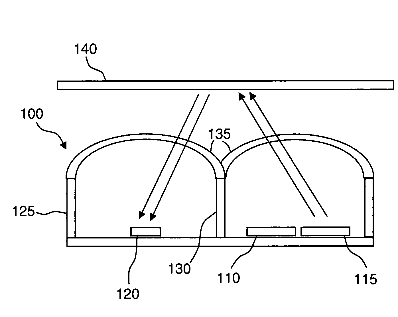
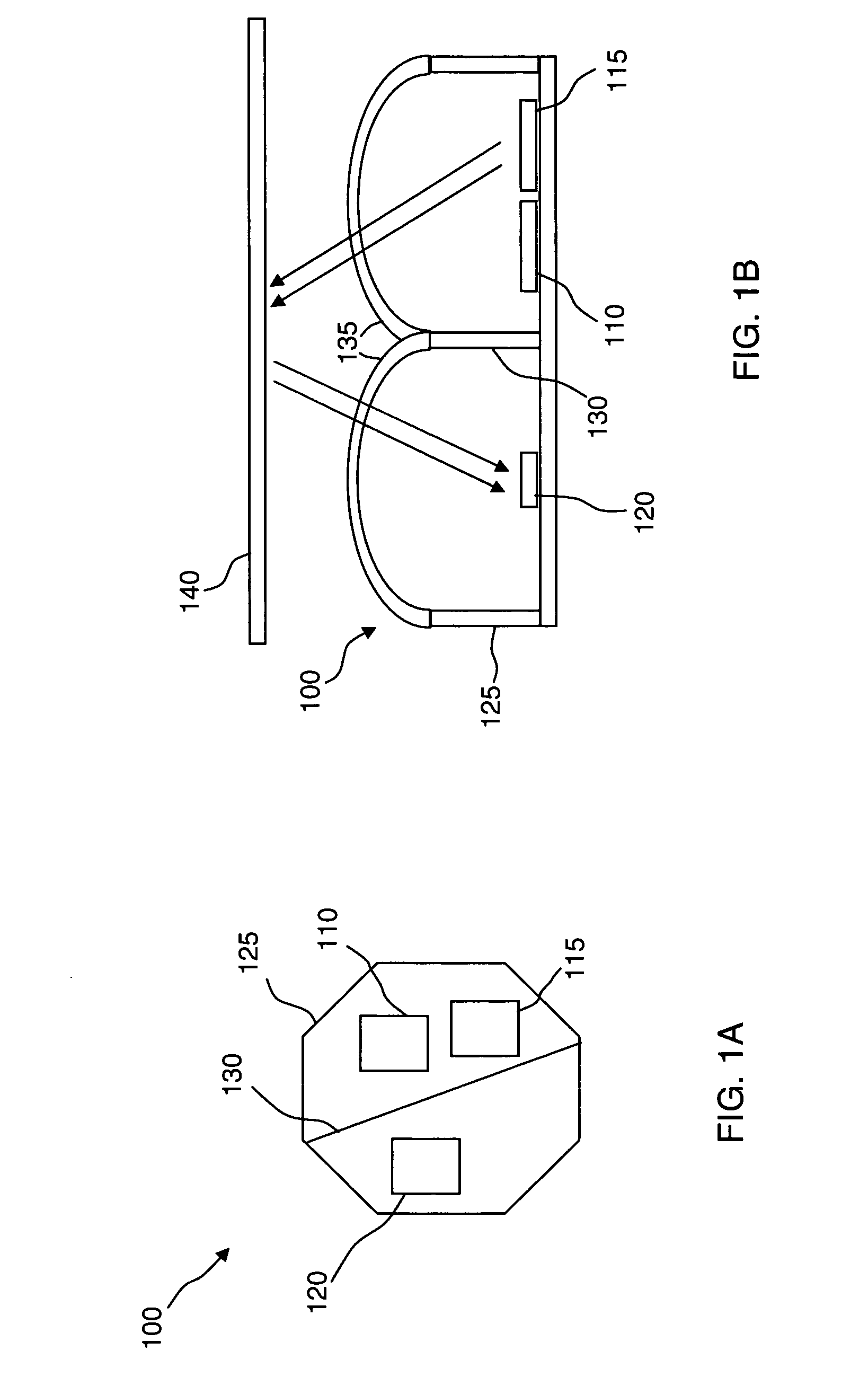
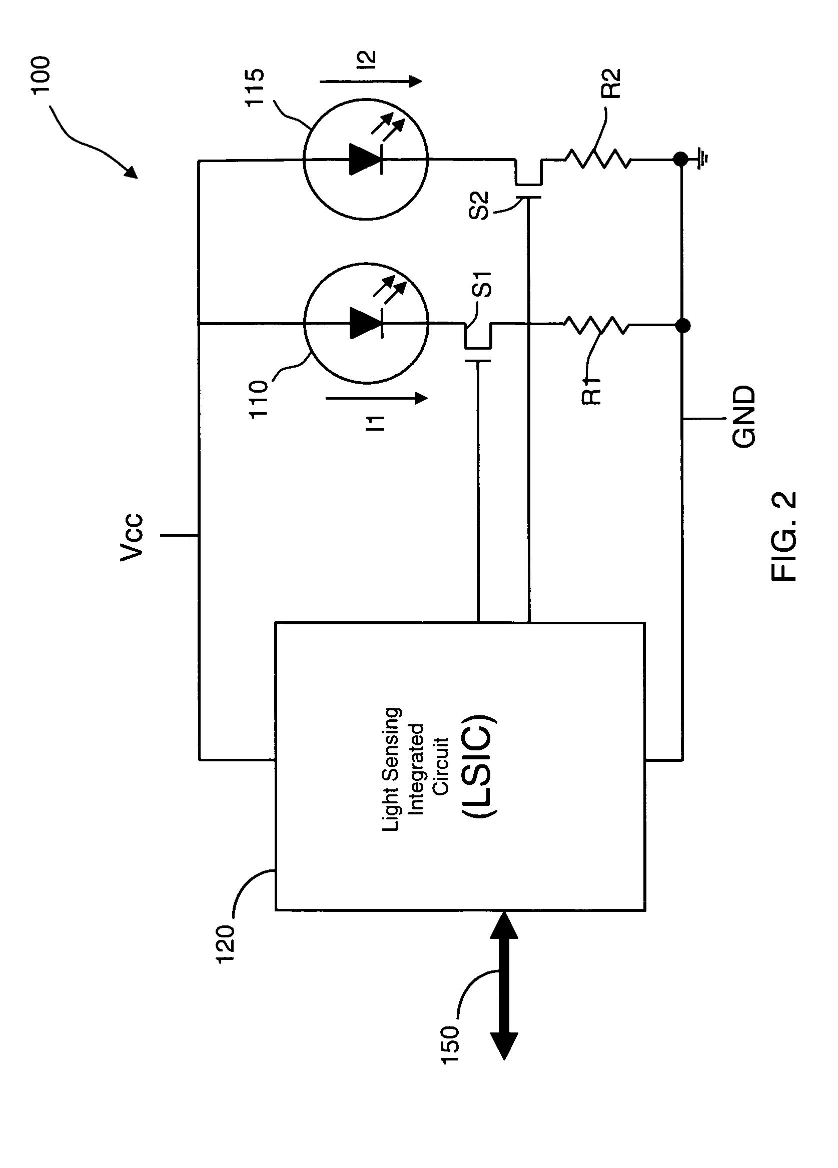
[0024]FIGS. 1A and 1B illustrate an integrated proximity and light sensor 100 that integrates one or more indicating light-emitting devices (“ILD's”) 110, a projecting light emitting device (“PLD”) 115, and a light sensing integrated circuit (“LSIC”) 120. In the present embodiment, the ILD 110, PLD 115, and LSIC 120 are enclosed in a protective light-isolation housing 125. The protective light-isolation housing 125 includes a light isolation partition 130 that separates the LSIC 120 from the PLD 115. In other embodiments, the ILD 110 and PLD 115 are also optically isolated from each other by a light isolation partition (not shown). The protective light-isolation housing 125 further includes one or more optics ports 135 disposed above a top surface thereof. The optics ports 135 may include lenses, optical flats, or other designs apparent to a person of skill in the art, and may be made from any material, such as glass or plastic, which is transparent or semitransparent to light in so...


PUM

PropertyMeasurementUnit
time periodaaaaaaaaaa
integration timeaaaaaaaaaa

Abstract

An integrated proximity and light sensor includes an indicating light-emitting device (“ILD”), a projecting light-emitting device (“PLD”), and a light sensing integrated circuit (“LSIC”) configured as a single package. The LSIC controls each of the ILD and the PLD to emit light therefrom and the LSIC is configured to detect an ambient light level and also to detect a reflection of the light projected by the PLD from a surface for proximity detection.

Description

CROSS REFERENCE TO RELATED APPLICATIONS[0001]This application claims the benefit of U.S. Provisional Patent Application Nos. 60 / 962,057 filed Jul. 25, 2007, and 61 / 003,099 filed Nov. 13, 2007. Each of the aforesaid applications is hereby incorporated by reference herein in its entirety.REFERENCE REGARDING FEDERALLY SPONSORED RESEARCH OR DEVELOPMENT[0002]Not applicableSEQUENTIAL LISTING[0003]Not applicableBACKGROUND OF THE INVENTION[0004]1. Technical Field[0005]This invention relates generally to the control of power supplied to a light source and other functions in an electronic device and, more particularly, to the use of light sensors to control the power supplied to such light source and the operation of such functions.[0006]2. Description of the Background[0007]Portable electronic devices, such as cellular phones and personal digital assistants, commonly include displays that are illuminated to facilitate interaction with a user. One challenge that arises with the illumination o...

Claims


Application Information

Patent Timeline
Patent Type & Authority Applications(United States)
IPC IPC(8): G01C3/08H01J40/14G01N21/55
CPCG01C3/08G01S7/4815H03K2217/94108H03K17/943G01S17/026G01S17/04
Inventor CHANG, TOMCANFIELD, JOHN
Owner EMINENT ELECTRONICS TECH
Why Eureka
Eureka Blog
Learn More