
Multifunction joystick apparatus and a method for using same

a multi-functional, joystick technology, applied in the direction of mechanical control devices, instruments, manual control with single controlling member, etc., can solve the problems of inability to accurately and/or accurately control the devices of simple joysticks, adversely affecting the operation of devices, etc., to achieve low power sleep zone and low power mode of operation

Active Publication Date: 2016-03-17
GRAYHILL
View PDF7 Cites 16 Cited by
  • Summary
  • Abstract
  • Description
  • Claims
  • Application Information

AI Technical Summary

Benefits of technology

The present invention provides a joystick apparatus with interchangeable functions, configurable structure, low power consumption, and the ability to distinguish between actual activation of the joystick and vibrations / minor disturbances. It allows for creating any one, two, or three functions on a single shaft of a push-button, pivoting, or rotating joystick in an up / down, side-to-side, or rotating direction.

Problems solved by technology

However, due to their simplicity and corresponding relatively low levels of performance, such joysticks may adversely affect the operation of the device.
Such simple joysticks have numerous limitations.
For example, such joysticks may not be capable of precise and / or accurate control of the devices.
Also, some of the simpler joysticks lack adjustability and / or adaptability for different applications.
The performance of the device may also be adversely impacted when such a limited joystick is used.
Consequently, device operation and / or user satisfaction and / or user safety may be negatively impacted when the joystick is inadequate.
Thus, many of the existing joysticks may be inadequate for controlling the performance of a device and / or may cause numerous performance and / or safety problems when operating a device.
However, the increase in complexity with such systems invariably may result in increased costs and / or reliability issues.

Method used


Image

  • Multifunction joystick apparatus and a method for using same
  • Multifunction joystick apparatus and a method for using same
  • Multifunction joystick apparatus and a method for using same

Examples


Embodiment Construction

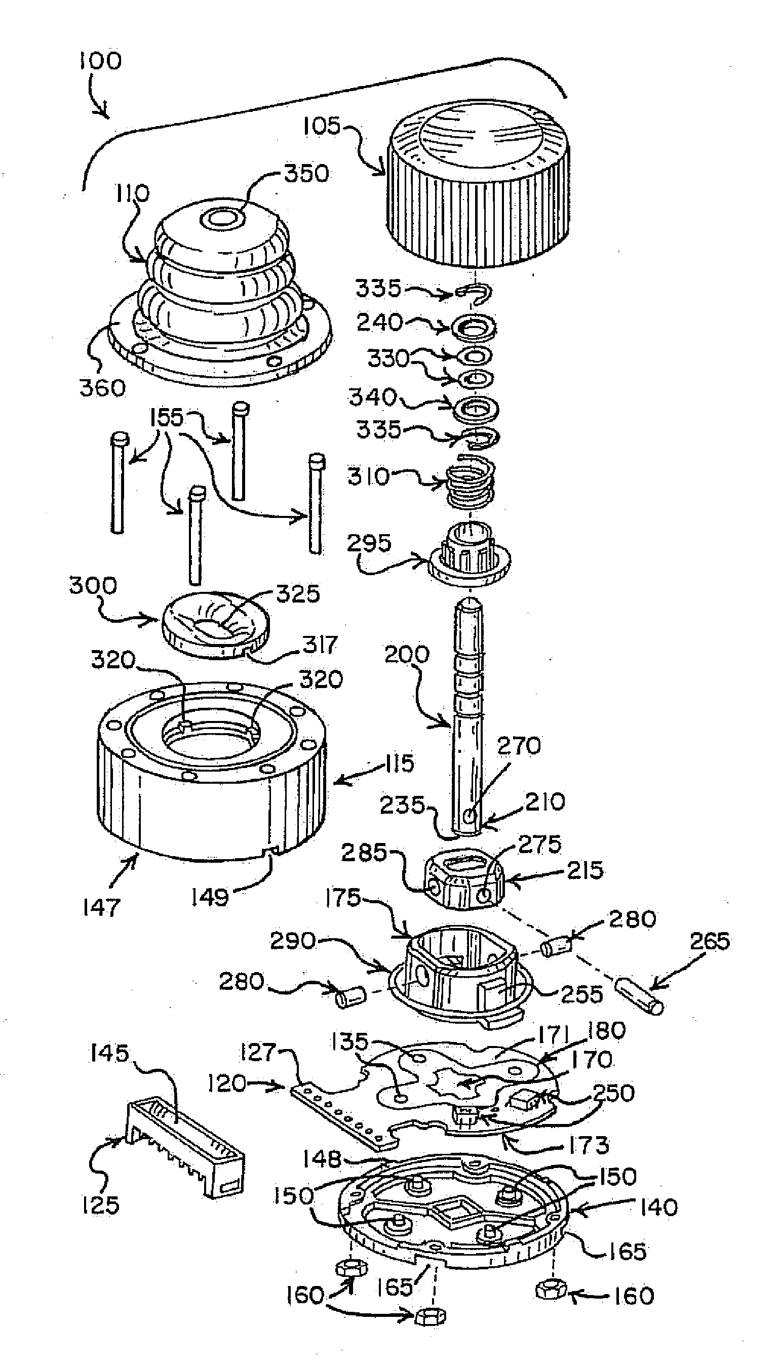
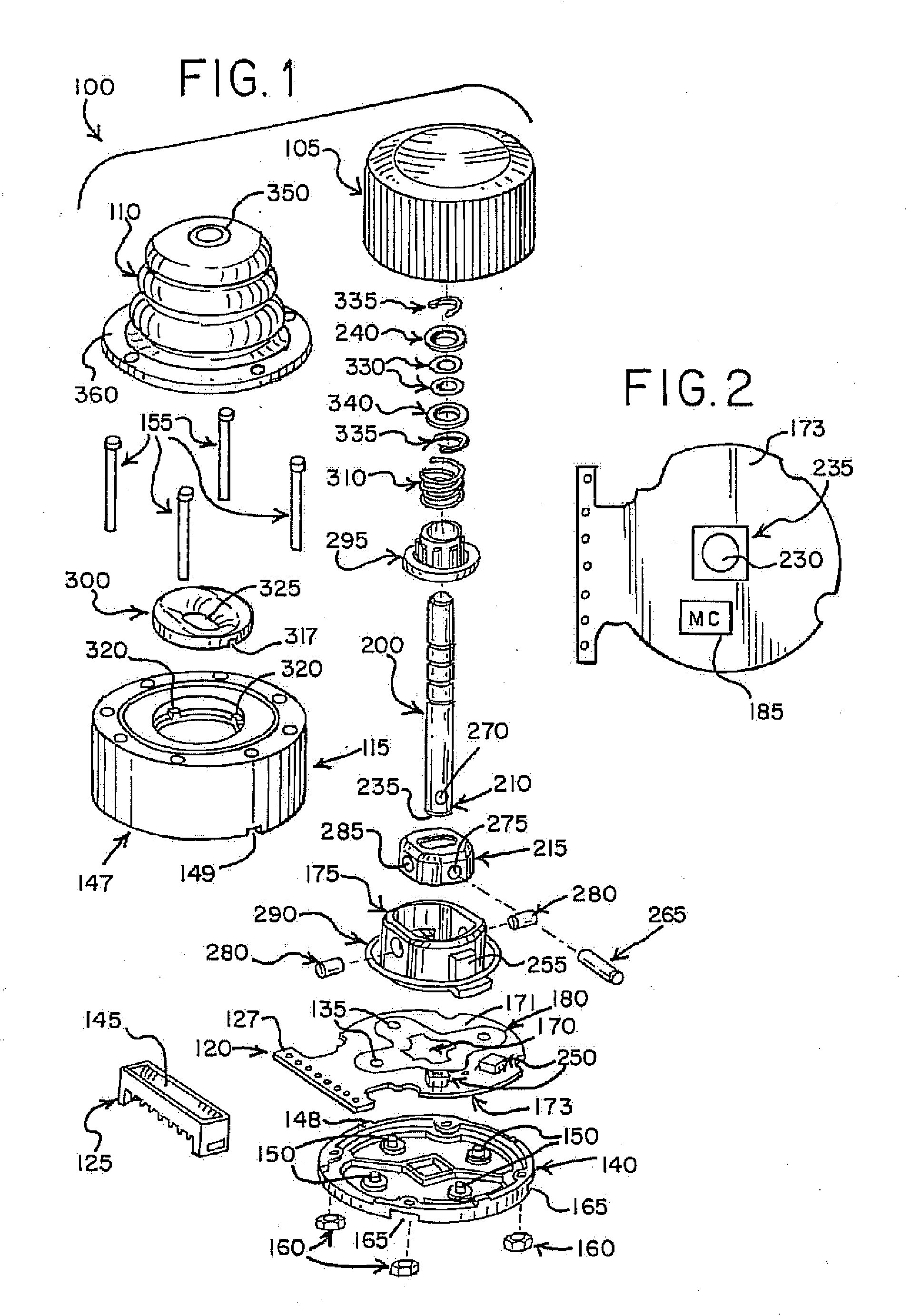
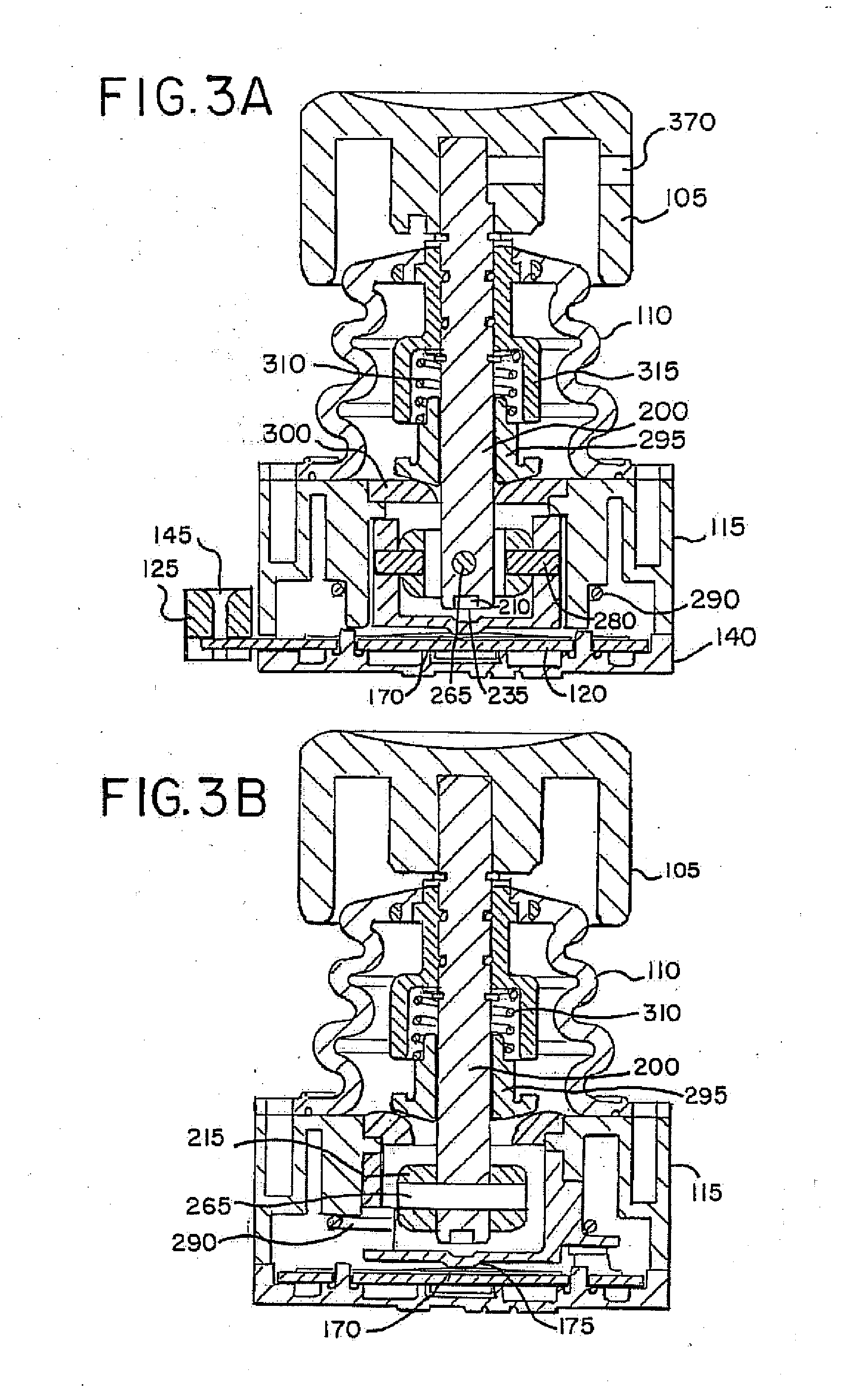
[0056]The present invention generally relates to a joystick apparatus and a method for using same. More specifically, the present invention relates to a joystick apparatus that may be configured in various embodiments to provide a multifunction joystick for a particular application and / or for a variety of devices.

[0057]To this end, in an embodiment, a joystick apparatus is provided. The apparatus has a housing and a printed circuit board in the housing. A U-joint assembly is positioned above the printed circuit board and has a U-joint rocker pivotably connected to a U-joint slider. The apparatus also has a shaft having a first end, a second end and a center position. The second end is pivotably connected to the U-joint rocker to allow movement of the shaft relative to the center position within a circle. The movement of the shaft is in at least one of a forward and a backward direction, a side-to-side direction, an axial direction or a rotating direction to provide an end user with ...


PUM


Abstract

A joystick apparatus has a housing and a printed circuit board in the housing. A shaft is pivotably connected to a U-joint assembly to allow movement of the shaft relative to the center position within a circle. A concentric reduced power zone circle is associated with the circle. Operation of the joystick within the reduced power zone circle uses less power than operation outside of the reduced power zone. A knob and a magnet are located on the shaft. A Hall effect integrated circuit detects movement of the magnet in response to corresponding movement of the shaft by a user and generates a corresponding proportional joystick output signal indicative of a direction and an extent of rotation of the shaft. A multifunction joystick control system has a joystick configured to provide multiple operational modalities on a joystick. An electrical interface connects the joystick apparatus and the host central processing unit.

Description

BACKGROUND OF THE INVENTION[0001]The present invention generally relates to a joystick input and control apparatus and a method for using same. The joystick provides control signals for controlling devices, machinery, computer games, or the like. More specifically, the present invention relates to a joystick apparatus that may be configured in various embodiments to provide a multifunction joystick for a particular application and / or for a variety of devices.[0002]Joysticks may be used to provide input control signals for controlling, for example, machinery, devices and computer application programs, such as computer games. A typical joystick has a handle that is pivotally rotatable about a base, producing an output signal corresponding to the angular displacement of the handle about orthogonal “X” and “Y” axes. The output signal from a joystick may typically be an input to a host device, such as a computer, which processes the signal. The signal may be used to control hardware or t...

Claims


Application Information

Patent Timeline
Patent Type & Authority Applications(United States)
IPC IPC(8): G05G9/047
CPCG05G9/047G05G2009/04759G05G2009/04755G05G2009/04718
Inventor CONRO, CHRISTOPHER M.KOZICH, STEPHEN
Owner GRAYHILL
Learn More