
System and method for light source identification

a technology for identification and light sources, applied in the field of lighting systems, can solve the problems of time-consuming and error-prone tasks, manual setting-up or programing of the control system, and cumbersome procedures for lighting systems with one or more independently controlled light sources

Inactive Publication Date: 2009-01-29
KONINKLIJKE PHILIPS ELECTRONICS NV
View PDF0 Cites 217 Cited by
  • Summary
  • Abstract
  • Description
  • Claims
  • Application Information

AI Technical Summary

Benefits of technology

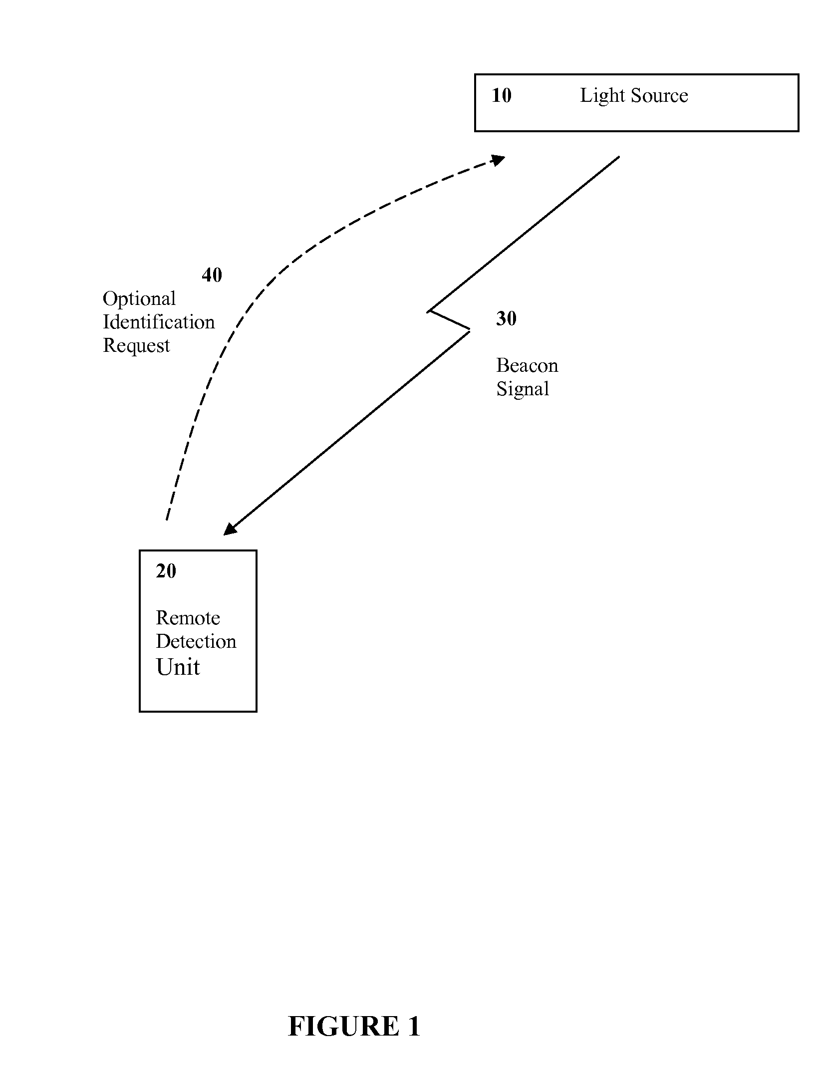
[0009]An object of the present invention is to provide a system and method for light source identification. In accordance with an aspect of the present invention, there is provided a system for light source identification, said system comprising: one or more light sources, each light source configured to emit light and further configured to integrate a beacon signal into the light, wherein the beacon signal of a specific light source includes a unique identifier of the specific light source; and a remote detection unit including one or more optical sensors, the remote detection unit configured to detect light emitted by the one or more light sources, the remote de...

Problems solved by technology

The installation and set-up of a lighting system with one or more independently controllable light sources can be a cumbersome procedure.
In addition to being a cumbersome procedure, the installation and set-up of a lighting system with one or more independently controllable light sources can also be an error prone procedure.
Furthermore, it can be a time consuming and error prone task to manually set-up or program a control system, with for example these unique identifiers which can provide a means for independently controlling the one or more light sources of the lighting system.
However, this disclosure does not address the initial wireless identification of the devices.

Method used


Image

  • System and method for light source identification
  • System and method for light source identification
  • System and method for light source identification

Examples


Embodiment Construction

Definitions

[0016]The term “light source” is used to define any device or collection of devices that emit radiation in a region or combination of regions of the electromagnetic spectrum.

[0017]The term “light-emitting element” is used to define any device that emits radiation in a region or combination of regions of the electromagnetic spectrum for example, the visible region, infrared and / or ultraviolet region, when activated by applying a potential difference across it or passing a current through it, for example. Therefore a light-emitting element can have monochromatic, quasi-monochromatic, polychromatic or broadband spectral emission characteristics. Examples of light-emitting elements include semiconductor, organic, or polymer / polymeric light-emitting diodes, optically pumped phosphor coated light-emitting diodes, optically pumped nano-crystal light-emitting diodes or other similar devices as would be readily understood by a worker skilled in the art. Furthermore, the term light...


PUM


Abstract

A light source is configured to send a beacon signal representative of the unique identifier thereof, on command, constantly or at a predetermined interval. The beacon signal is integrated into the light emitted by the light source, wherein the integration of the beacon signal is performed in a manner that visible flicker of the resultant light is imperceptible. A remote detection unit is configured to receive the light and extract the beacon signal therefrom. In this manner the remote detection device is capable of wirelessly determining the unique identifier of a light source. The collected unique identifier of the light source can subsequently be provided to a controller associated with the light source, thereby providing individual control of the light source by the controller. Through the use of electronic data transfer from the remote detection unit to the controller, the provision of the one or more unique identifiers to the controller can be enabled in an efficient and accurate manner.

Description

FIELD OF THE INVENTION[0001]The present invention pertains to lighting systems and in particular to identification of light sources associated with lighting systems.BACKGROUND[0002]The installation and set-up of a lighting system with one or more independently controllable light sources can be a cumbersome procedure. Each light source must be individually addressable if it is desired to control the operating conditions of the light sources independently. Observation of a change in operating conditions of each light source through identification, addressing, and control of that light source can be achieved in various different ways including the initial identification and address allocation during installation.[0003]In addition to being a cumbersome procedure, the installation and set-up of a lighting system with one or more independently controllable light sources can also be an error prone procedure. This is due in part because of the menial but required task of assigning a unique ...

Claims


Application Information

Patent Timeline
IPC IPC(8): H05B39/04H05B37/00
CPCH05B37/0272H05B37/0245H05B47/175H05B47/195H05B47/199
Inventor ROBINSON, SHANE
Owner KONINKLIJKE PHILIPS ELECTRONICS NV
Learn More