
Frequency modulation in the optical alignment of wavelength-converted laser sources

a laser source and wavelength conversion technology, applied in semiconductor lasers, laser controllers, instruments, etc., can solve the problems of difficulty in properly aligning the beam from the laser diode and the waveguide of the shg crystal, and achieve the effect of reducing the cost and eliminating some relatively intensive alignment procedures

Inactive Publication Date: 2009-01-22
CORNING INC
View PDF11 Cites 27 Cited by
  • Summary
  • Abstract
  • Description
  • Claims
  • Application Information

AI Technical Summary

Benefits of technology

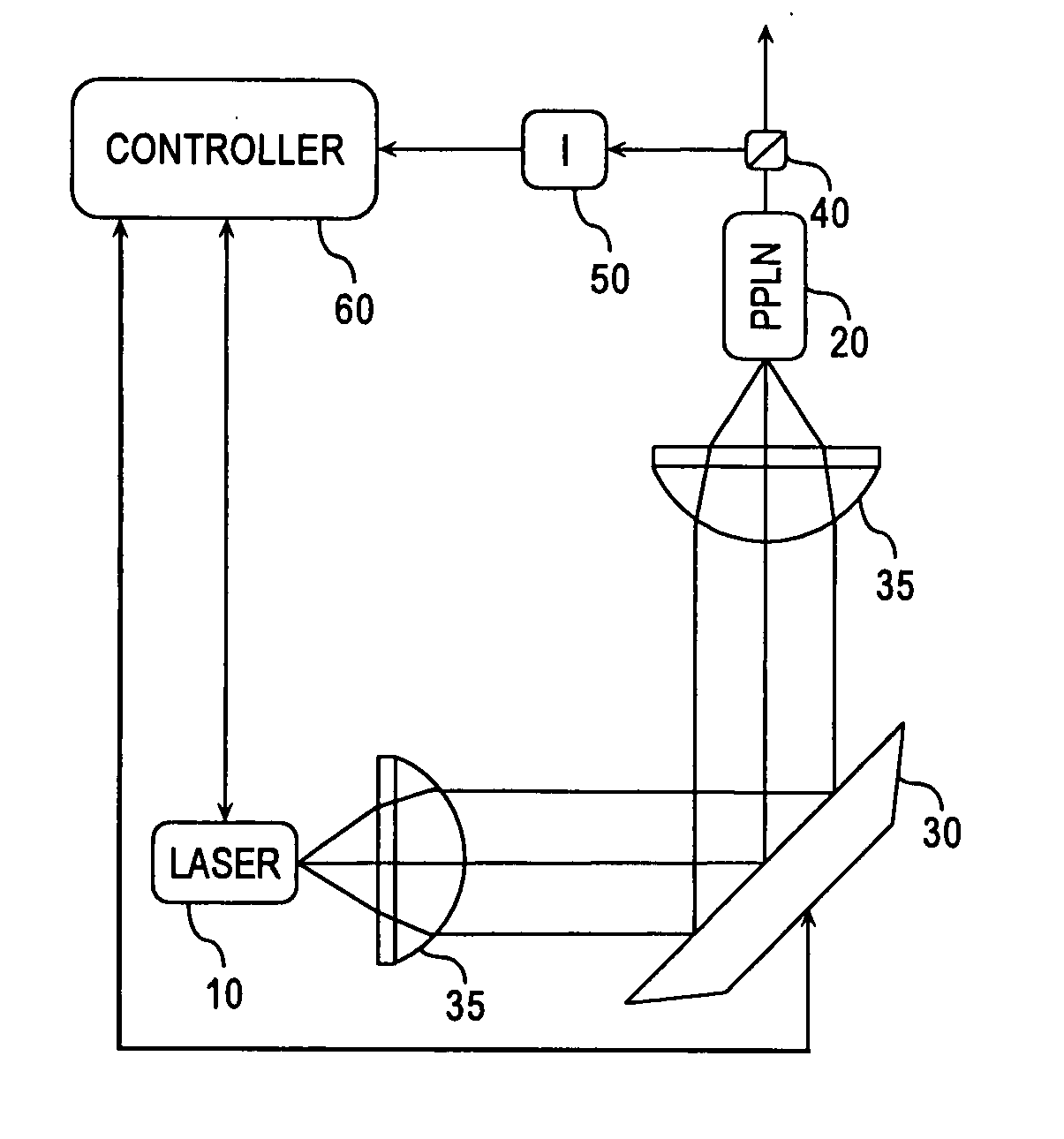
[0006]Still further embodiments of the present invention relate to laser projection systems and laser controllers programmed to operate semiconductor lasers according to the concepts of the present invention. It is contemplated that various concepts of the present invention will be applicable to color image-forming laser projection systems, laser-based displays such as heads-up displays in automobiles, or any laser application where optical alignment and / or wavelength tuning are issues. It is further contemplated that the control schemes discussed herein will have utility in a variety of types of semiconductor lasers, including but not limited to DBR and DFB lasers, Fabry-Perot lasers, and many types of external cavity lasers. Finally, it is contemplated that the various embodiment of the present invention, where adjustable optical components are configured to enable the aforementioned alignment accuracy, will permit construction and assembly of optical packages with increased ease and at substantially lower cost because they can allow for the elimination of some relatively intensive alignment procedures typically used in device assembly.

Problems solved by technology

As a result, the present inventors have recognized that it can be very challenging to align the beam from the laser diode and the waveguide of the SHG crystal properly.

Method used


Image

  • Frequency modulation in the optical alignment of wavelength-converted laser sources
  • Frequency modulation in the optical alignment of wavelength-converted laser sources
  • Frequency modulation in the optical alignment of wavelength-converted laser sources

Examples


Embodiment Construction

[0012]Although the general structure of the various types of optical packages in which the concepts of particular embodiments of the present invention can be incorporated is taught in readily available technical literature relating to the design and fabrication of frequency or wavelength-converted semiconductor laser sources, the concepts of particular embodiments of the present invention may be conveniently illustrated with general reference to an optical package including, for example, a DBR-type near-infrared semiconductor laser and a frequency-doubling PPLN SHG crystal. In such a configuration, the near infrared light emitted by the semiconductor laser is either directly coupled into the waveguide of the SHG wavelength conversion device or is coupled into the waveguide through collimating and focusing optics or some other type of suitable optical element or optical system. The wavelength conversion device converts the incident near-infrared light into frequency-doubled green las...


PUM

PropertyMeasurementUnit
deflection angleaaaaaaaaaa
wavelengthsaaaaaaaaaa

Abstract

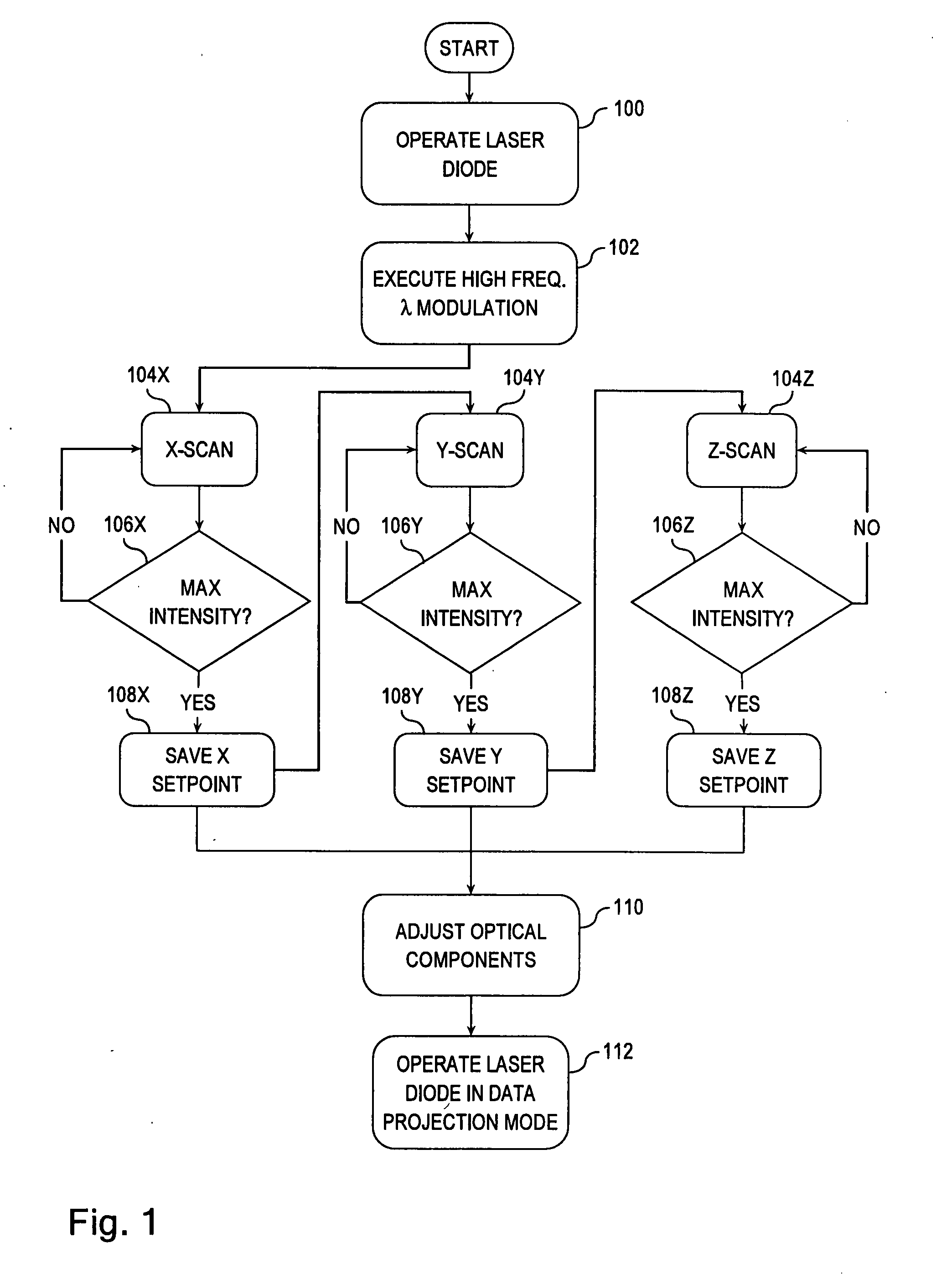
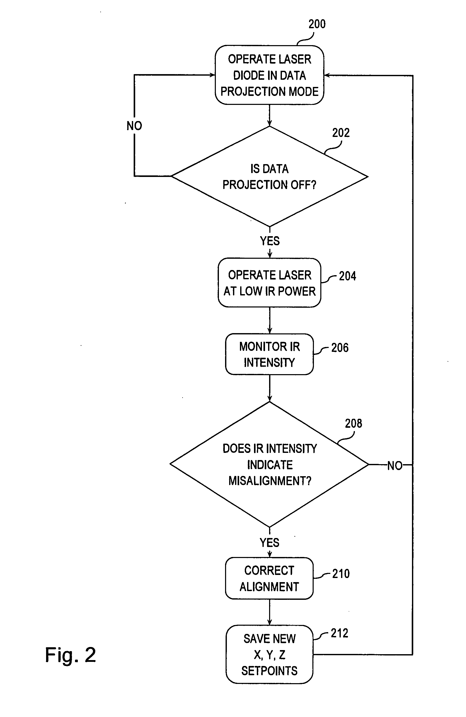
Methods of controlling semiconductor lasers are provided where the semiconductor laser generates a wavelength-modulated output beam λMOD that is directed towards the input face of a wavelength conversion device. The intensity of a wavelength-converted output λCONV of the device is monitored as the output beam of the laser is modulated and as the position of the modulated output beam λMOD on the input face of the wavelength conversion device is varied. A maximum value of the monitored intensity is correlated with optimum coordinates representing the position of the modulated output beam λMOD on the input face of the wavelength conversion device. The optical package is operated in the data projection mode by directing an intensity-modulated laser beam from the semiconductor laser to the wavelength conversion device using the optimum positional coordinates. Additional embodiments are disclosed and claimed. Laser controllers and projections systems are also provided.

Description

SUMMARY OF THE INVENTION[0001]The present invention relates generally to semiconductor lasers, laser controllers, laser projection systems, and other optical systems incorporating semiconductor lasers. More particularly, by way of illustration and not limitation, embodiments of the present invention relate generally to optical alignment in packages that include, inter alia, a semiconductor laser and a second harmonic generation (SHG) crystal or another type of wavelength conversion device.[0002]Short wavelength light sources can be formed by combining a single-wavelength, relatively long semiconductor laser, such as an infrared or near-infrared distributed feedback (DFB) laser, distributed Bragg reflector (DBR) laser, or Fabry-Perot laser, with a light wavelength conversion device, such as a second harmonic generation (SHG) crystal. Typically, the SHG crystal is used to generate higher harmonic waves of the fundamental laser signal. To do so, the lasing wavelength is preferably tune...

Claims


Application Information

Patent Timeline
Patent Type & Authority Applications(United States)
IPC IPC(8): G02F1/37G02F1/35
CPCG02F1/377H01S5/0687H01S5/0622G02F2001/3546G02F1/3546
Inventor ALMORIC, ETIENNEBHATIA, VIKRAMGOLLIER, JACQUESPIKULA, DRAGANRICKETTS, DANIEL OHEN
Owner CORNING INC
Learn More