
Reception device, reception method, and computer-readable medium

a technology of reception device and reception method, applied in the field of reception device for receiving multicast distribution data and a reception method, can solve problems such as channel switchover delay, and achieve the effect of reducing the time required to switch channels

Inactive Publication Date: 2009-01-22
SONY CORP
View PDF5 Cites 181 Cited by
  • Summary
  • Abstract
  • Description
  • Claims
  • Application Information

AI Technical Summary

Benefits of technology

[0014]According to the embodiments described above, the multicast media access control addresses for the channels being distributed by the distribution servers may be registered in advance, and the time required to switch channels can be reduced. Thus, a new and improved reception device, reception method, and computer program are provided that allow the time required to switch channels to be reduced.

Problems solved by technology

The time required to set the multicast MAC address when switching channels, however, results in a channel switchover delay.

Method used


Image

  • Reception device, reception method, and computer-readable medium
  • Reception device, reception method, and computer-readable medium
  • Reception device, reception method, and computer-readable medium

Examples


first embodiment

[0028]First, a reception device and a reception method using the reception device, will be explained.

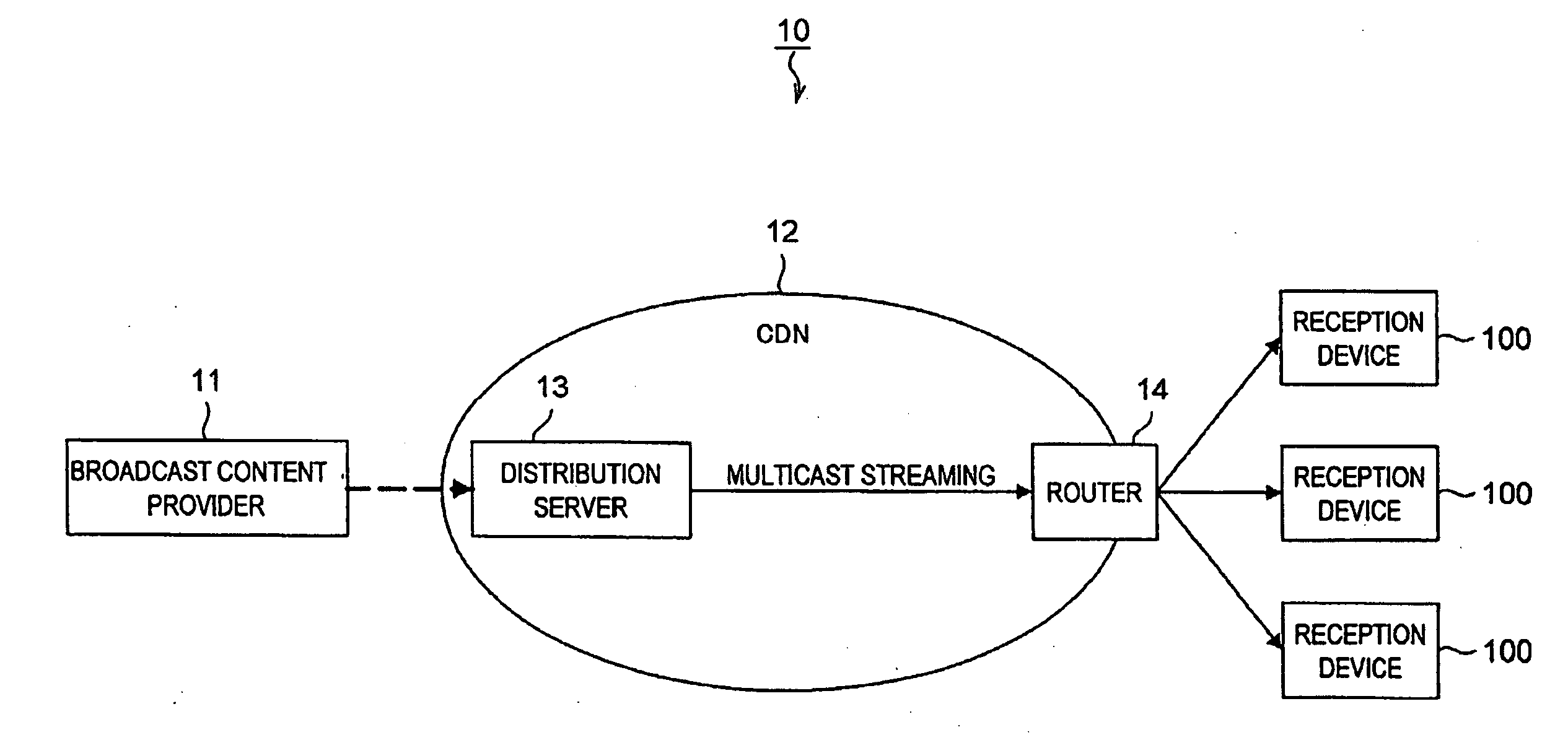
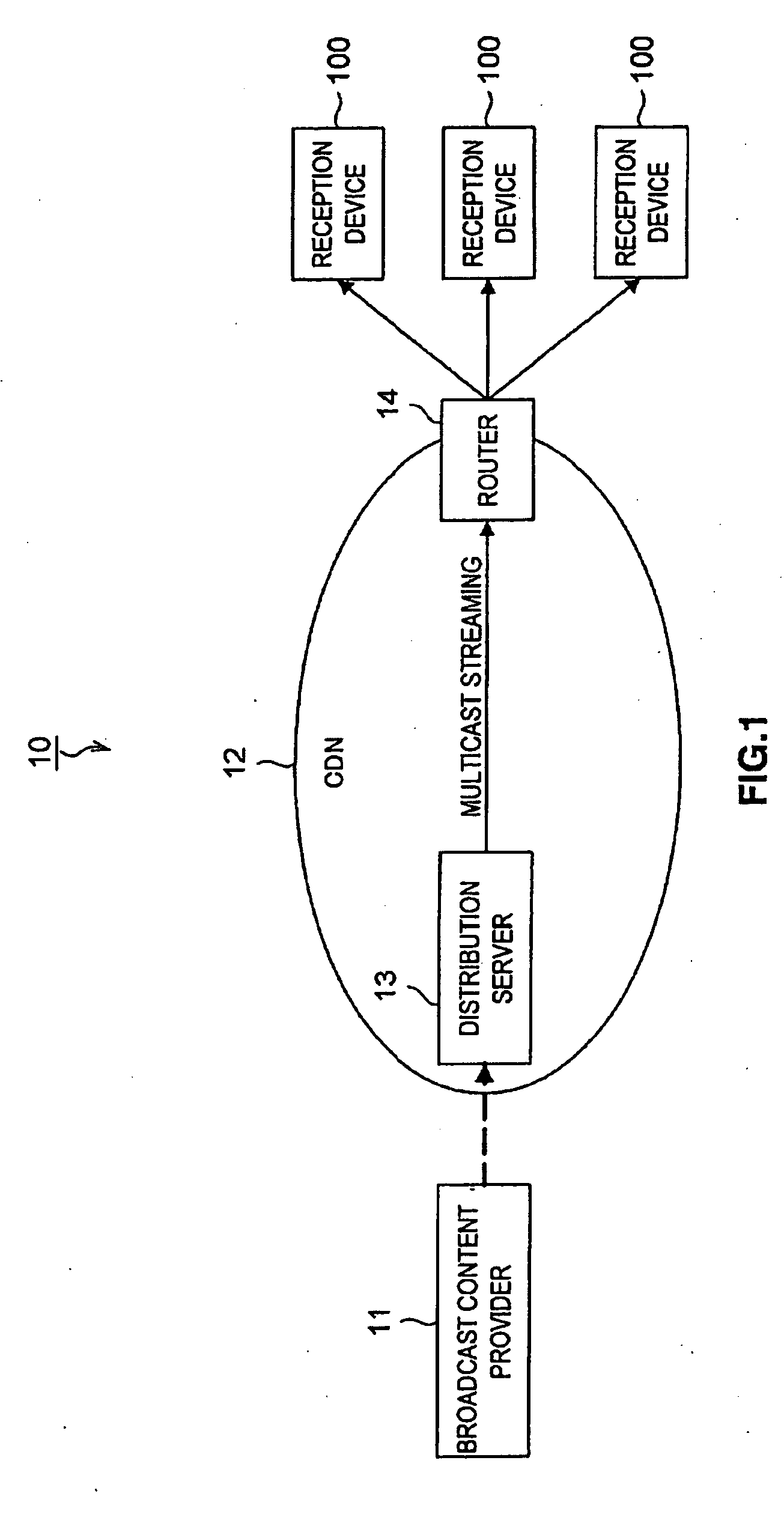
[0029]FIG. 1 is an explanatory diagram illustrating a multicast distribution system 10 using a reception device 100 according to the first embodiment.

[0030]As shown in FIG. 1, the multicast distribution system 10 may include a distribution server 13 that allows a broadcast content provider 11 to distribute content, and a router 14 that may receive the content and transmit the content to the destination reception device 100.

[0031]The distribution server 13 and the router 14 may be connected by a content delivery network (CDN) 12. The CDN 12 may be a network optimized to distribute digital content with a large file size via the network.

[0032]The distribution server 13 may control distribution of the multicast content data, such as Internet Protocol Television (IPTV) content and the like. The distribution server may also distribute image and voice media streams for the multicast conten...

second embodiment

[0102]In a second embodiment, reducing the channel switching time will be explained where there are a plurality of reception devices receiving the content within one network segment (e.g., within one household).

[0103]FIG. 11 is an explanatory diagram illustrating a multicast distribution system according to the second embodiment. The multicast distribution system according to the second embodiment will be explained with reference to FIG. 11.

[0104]As shown in FIG. 11, the multicast distribution system may include, among other things, a plurality of distribution servers 200, a home gateway (HGW) 220, a personal computer 230, a DVD recorder 240, a hard disk recorder 250, and a television 260.

[0105]The distribution servers 200, similar to the distribution server 13 in the first embodiment, may manage the multicast content data for IPTV content and the like, and, in response to a request from a reception device, may distribute the multicast content image and audio media streams to recept...


PUM


Abstract

A reception device and method are provided for receiving content on channels distributed by distribution servers via a router. The method includes registering a multicast media access control address corresponding to a channel to be switched to before switching to the channel; storing the multicast media access control address; and switching to the channel using the stored multicast media access control address.

Description

CROSS REFERENCE[0001]The present invention contains subject matter related to Japanese Patent Application JP 2007-188181, filed in the Japanese Patent Office on Jul. 19, 2007, the contents of which are incorporated herein by reference.TECHNICAL FIELD[0002]The invention relates to a reception device, a reception method, and a computer-readable medium. Specifically, the invention relates to a reception device for receiving multicast distribution data and a reception method.BACKGROUND INFORMATION[0003]With recent advances in network technology, programs (e.g., content) are distributed through networks. Providers that distribute programs convert the programs to Internet Protocol (IP) packets, and then distribute the programs from servers using multicast distribution, where the same signal is distributed to a plurality of recipients. The protocols generally used to receive the multicast distribution programs include Internet Group Management Protocol (IGMP) for Ipv4 network environments ...

Claims


Application Information

Patent Timeline
IPC IPC(8): H04L12/56H04N7/173H04L12/70H04N21/435H04N21/442
CPCH04L12/185H04L45/16H04L12/1877H04L12/1859
Inventor KIRIBE, MASAHIROKATAYAMA, YASUSHI
Owner SONY CORP
Learn More