Heat diffusing device and method of producing the same

Inactive Publication Date: 2009-01-22
SONY CORP
View PDF12 Cites 16 Cited by
  • Summary
  • Abstract
  • Description
  • Claims
  • Application Information

AI Technical Summary

Benefits of technology

[0009]In view of the aforementioned points, it is desirable to provide a heat diffusing device which makes it possible to precisely form grooves defined by steep wall faces and to provide good heat diffusion, and a method of producing the same.
[0011]In the embodiment of the present invention, since the first and second metallic thin plates whose dimensions differ are alternately laminated, a groove defined by a steep wall face is formed with good precision at the wall face defining the sealed space. Since a contact angle θ of the liquid with respect to the wall face defining the groove can be made small, water is efficiently evaporated.
[0014]According to the heat diffusing device according to one embodiment of the present invention, a groove defined by steep wall face is formed, and the liquid in the groove can be evaporated with good efficiency. Therefore, a heat diffusing device providing good heat diffusion can be provided.

Problems solved by technology

As a result, grooves defined by steep wall faces cannot be formed.

Method used


Image

  • Heat diffusing device and method of producing the same
  • Heat diffusing device and method of producing the same
  • Heat diffusing device and method of producing the same

Examples


first embodiment

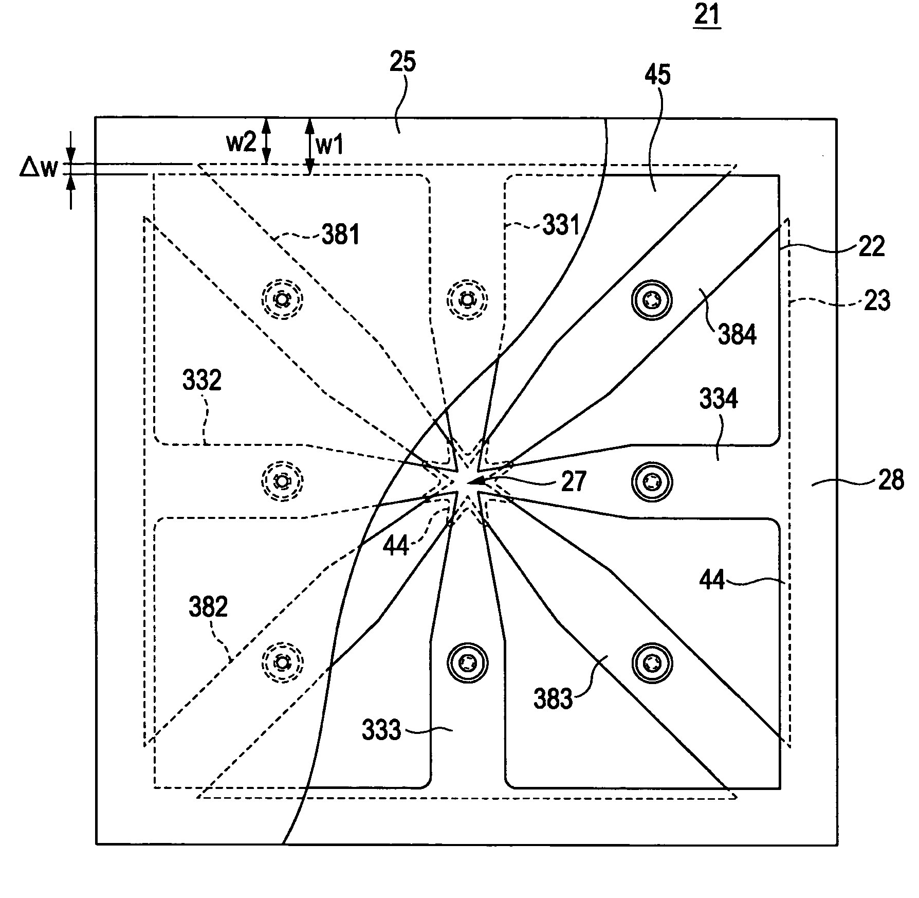
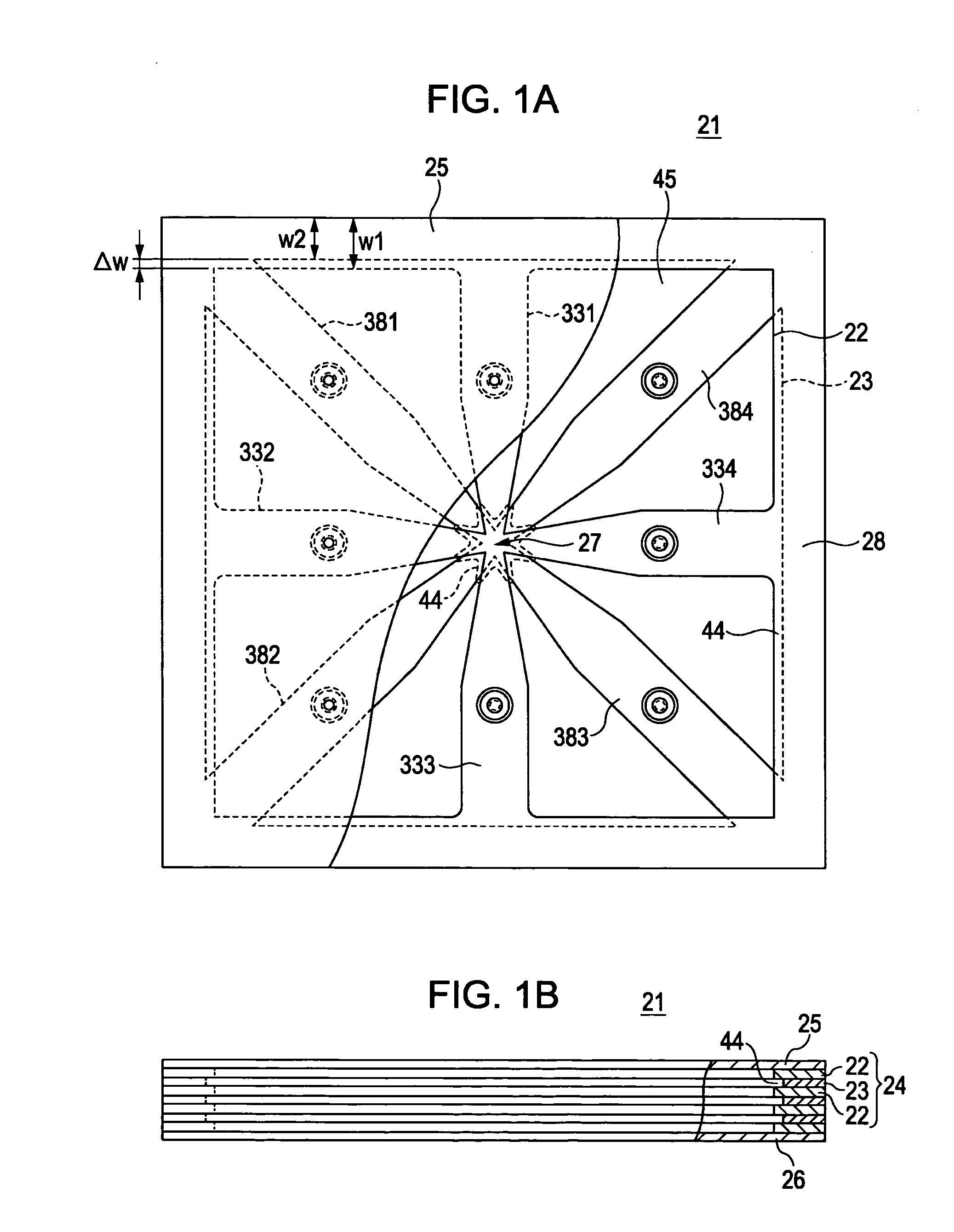
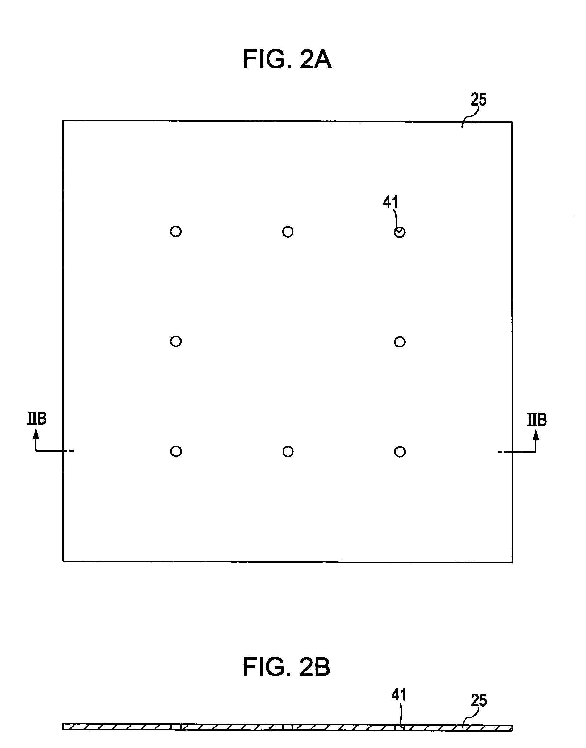
[0040]FIGS. 1 to 5 illustrate a heat diffusing device and a method of producing the same according to the present invention. As shown in FIGS. 1A and 1B, a heat diffusing device 21 according to the embodiment includes a laminated body 24 and sealing metallic plates 25 and 26. The laminated body 24 includes first metallic thin plates 22 and second metallic thin plates 23, which are alternately laminated, and which have rectangular contour shapes, that is, rectangular contour shapes of the same size in the embodiment, as viewed from above. The dimensions of the second metallic thin plates 23 differ from those of the first metallic thin plates 22. The sealing metallic thin plates 25 and 26 seal the top and bottom of the laminated body 24, respectively. The first and second metallic thin plates 22 and 23 have the same film thickness. The upper and lower sealing metallic thin plates 25 and 26 also have the same film thickness.

[0041]As shown in FIGS. 3A and 3B, each first metallic thin pl...

second embodiment

[0058]FIGS. 12 to 17 show a heat diffusing device and a method of producing the same according to the present invention. As shown in FIGS. 12 and 13, a heat diffusing device 61 according to the embodiment includes a laminated body 64 and sealing metallic thin plates 65 and 66 that seal the upper and lower sides of the laminated body 64. In the laminated body 64, first metallic thin plates 62 and second metallic thin plates 63 are alternately laminated, and have rectangular shapes in which a long side of a contour shape is sufficiently longer than a short side of the contour shape as viewed from above. The dimensions of each second metallic thin plate 63 differ from those of each first metallic thin plate 62. The first and second metallic thin plates 62 and 63 have the same thickness. The upper sealing metallic thin plate 65 and the lower sealing metallic thin plate 66 also have the same thickness.

[0059]As shown in FIGS. 14A to 14C, each first metallic thin plate 62 is formed into a ...


PUM

PropertyMeasurementUnit
Pressureaaaaaaaaaa

Abstract

A heat diffusing device includes first and second metallic thin plates that are alternately laminated to each other, and that are joined along with an upper sealing metallic thin plate and a lower sealing metallic thin plate by diffusion joining so as to form a sealed space in an interior defined by the first and second thin plates and the upper and lower sealing metallic thin plates. A C-shaped groove defined by a steep wall face is formed at a wall face defining the sealed space due to a difference (Δw) between the dimensions of the first metallic thin plates and the dimensions of the second metallic thin plates.

Description

CROSS REFERENCES TO RELATED APPLICATIONS[0001]The present invention contains subject matter related to Japanese Patent Application JP 2007-188373 filed in the Japanese Patent Office on Jul. 19, 2007, the entire contents of which are incorporated herein by reference.BACKGROUND OF THE INVENTION[0002]1. Field of the Invention[0003]The present invention relates to a heat diffusing device that restricts the temperature of a heat source to a temperature less than or equal to a predetermined temperature by diffusing heat of the heat source in, for example, an electronic apparatus or other apparatuses.[0004]2. Description of the Related Art[0005]Hitherto, in, for example, an electronic apparatus, such as a personal computer or a projector (display apparatus), a heat diffusing device for dissipating heat of a heat source is required. What is called a heat pipe is known as an example of the heat diffusing device. The heat pipe has, for example, the following structure. That is, for example, a...

Claims


Application Information

Patent Timeline
IPC IPC(8): F28F3/12
CPCF28D15/0233F28D15/0266F28F3/12Y10T29/4935H01L2924/0002H01L23/427H01L2924/00
Inventor KAWABATA, YASUO
Owner SONY CORP
Why Eureka
Try Eureka