Eureka AIR delivers breakthrough ideas for toughest innovation challenges, trusted by R&D personnel around the world.

Pneumatically-Powered Intraocular Lens Injection Device with Removable Cartridge

a technology of ophthalmic injection and pneumatic power, which is applied in the field of single-use medical devices, can solve the problems of affecting the accuracy of intraocular lens injection,

Inactive Publication Date: 2009-01-15
ALCON INC
View PDF53 Cites 53 Cited by
  • Summary
  • Abstract
  • Description
  • Claims
  • Application Information

AI Technical Summary

Problems solved by technology

The volume injected is typically not controlled in an accurate manner because the vernier on the syringe is not precise relative to the small injection volume.
Fluid flow rates are uncontrolled.
Reading the vernier is also subject to parallax error.
Tissue damage may occur due to an “unsteady” injection.
When age or disease causes the natural lens to become less transparent, vision deteriorates because of the diminished light which can be transmitted to the retina.

Method used


Image

  • Pneumatically-Powered Intraocular Lens Injection Device with Removable Cartridge
  • Pneumatically-Powered Intraocular Lens Injection Device with Removable Cartridge
  • Pneumatically-Powered Intraocular Lens Injection Device with Removable Cartridge

Examples


Embodiment Construction

[0020]Reference is now made in detail to the exemplary embodiments of the invention, examples of which are illustrated in the accompanying drawings. Wherever possible, the same reference numbers are used throughout the drawings to refer to the same or like parts.

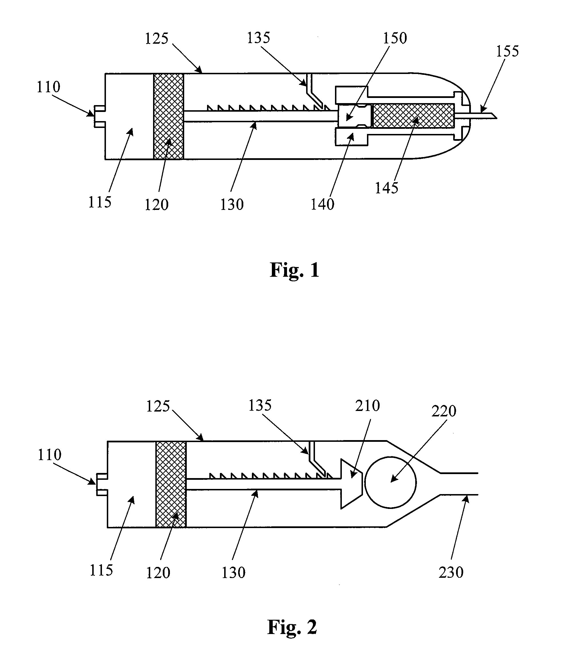
[0021]FIG. 1 is a cross section view of a pneumatically-driven ophthalmic injection device according to an embodiment of the present invention. In FIG. 1, the injection device includes a port 110, a chamber 115, a piston 120, a housing 125, a shaft 130, a pawl 135, a dispensing chamber housing 140, a dispensing chamber 145, a plunger 150, and a needle 155.

[0022]Port 110 is located on one end of the injection device, and needle 155 is located on the other end. A housing 125 encloses the various components depicted and forms an outer skin. Chamber 115 is fluidly coupled to port 110. Chamber 115 is configured to receive air (or a suitable gas or fluid) through port 110. Piston 120 is disposed in chamber 115 and forms one bounda...


PUM


Abstract

A device for injecting an intraocular lens into an eye includes a compartment for holding an intraocular lens, a plunger engaged with the compartment, a nozzle coupled to the compartment, and a pneumatic cylinder. The pneumatic cylinder has a chamber and a cylinder connected to a shaft. The shaft is connected to the plunger. The shaft has teeth located on its surface. A pawl engages the teeth to limit the movement of the shaft to a dispensing direction. Pneumatic pressure introduced into the chamber moves the piston, shaft, and plunger in the dispensing direction so as to push the intraocular lens through the nozzle

Description

BACKGROUND OF THE INVENTION[0001]The present invention relates to a single-use medical device and more particularly to an pneumatically-powered ophthalmic injection device for injecting a precise amount of a pharmaceutical, viscoelastic, perflurocarbon liquid, IOL, or the like.[0002]Several diseases and conditions of the posterior segment of the eye threaten vision. Age related macular degeneration (ARMD), choroidal neovascularization (CNV), retinopathies (e.g., diabetic retinopathy, vitreoretinopathy), retinitis (e.g., cytomegalovirus (CMV) retinitis), uveitis, macular edema, glaucoma, and neuropathies are several examples.[0003]These, and other diseases, can be treated by injecting a drug into the eye. Such injections are typically manually made using a conventional syringe and needle. In using such a syringe, the surgeon is required to puncture the eye tissue with the needle, hold the syringe steady, and actuate the syringe plunger (with or without the help of a nurse) to inject ...

Claims


Application Information

Patent Timeline
Patent Type & Authority Applications(United States)
IPC IPC(8): A61F9/007
CPCA61F2/1662A61F2/1678A61F2/167
Inventor CHARLES, STEVEN T.
Owner ALCON INC
Why Eureka
Eureka Blog
Learn More