Packaging system

Inactive Publication Date: 2009-01-08
TORAY ENG CO LTD
View PDF3 Cites 16 Cited by
  • Summary
  • Abstract
  • Description
  • Claims
  • Application Information

AI Technical Summary

Benefits of technology

[0013]In the mounting system according to the present invention, the mounting can be carried out at a stable dimensional condition by preventing the moisture absorption of the substrate and always keeping the temperature of the substrate at a constant temperature. Further, defects due to delamination of mounting interface, etc. at the time of curing in the oven after performing underfill can be decreased. By employing the system for mounting the substrate on the carrier with a great thermal capacity and conveying the substrate by the carrier, a better heat insulation performance can be obtained.
[0014]Further, b

Problems solved by technology

In the step for sequentially loading the substrates toward the chip mounting section, however, because a substrate loaded from the substrate magazine at a latter stage is likely to absorb moisture in the atmosphere as the time passes, when an underfill agent (a resin) is cured after an underfill process (a process for providing a resin between the substrate and the chip), a problem may occur in that a delamination of mounting interface or voids occur by a volume expansion or evaporation of the moisture absorbed into the substrate.
Further, because a change in volume occurs by the moisture absorption, the substrate is likely to be bowed.
If the substrate bows, there occurs a problem that a proper bonding between a bump and an electrode may not be performed between the chip and the substrate.
In these conventional technologies, however, even if a heating or a heat insulating can be achieved at a certain step in the mounting process having a series of steps, since it is difficult to sustain a substrate at a desirable temperature over the entire mounting process, it is difficult to completely solve the aforementioned problems ascribed to moisture absorption.

Method used


Image

  • Packaging system
  • Packaging system
  • Packaging system

Examples


Embodiment Construction

[0049]Hereinafter, desirable embodiments of the present invention will be explained referring to figures.

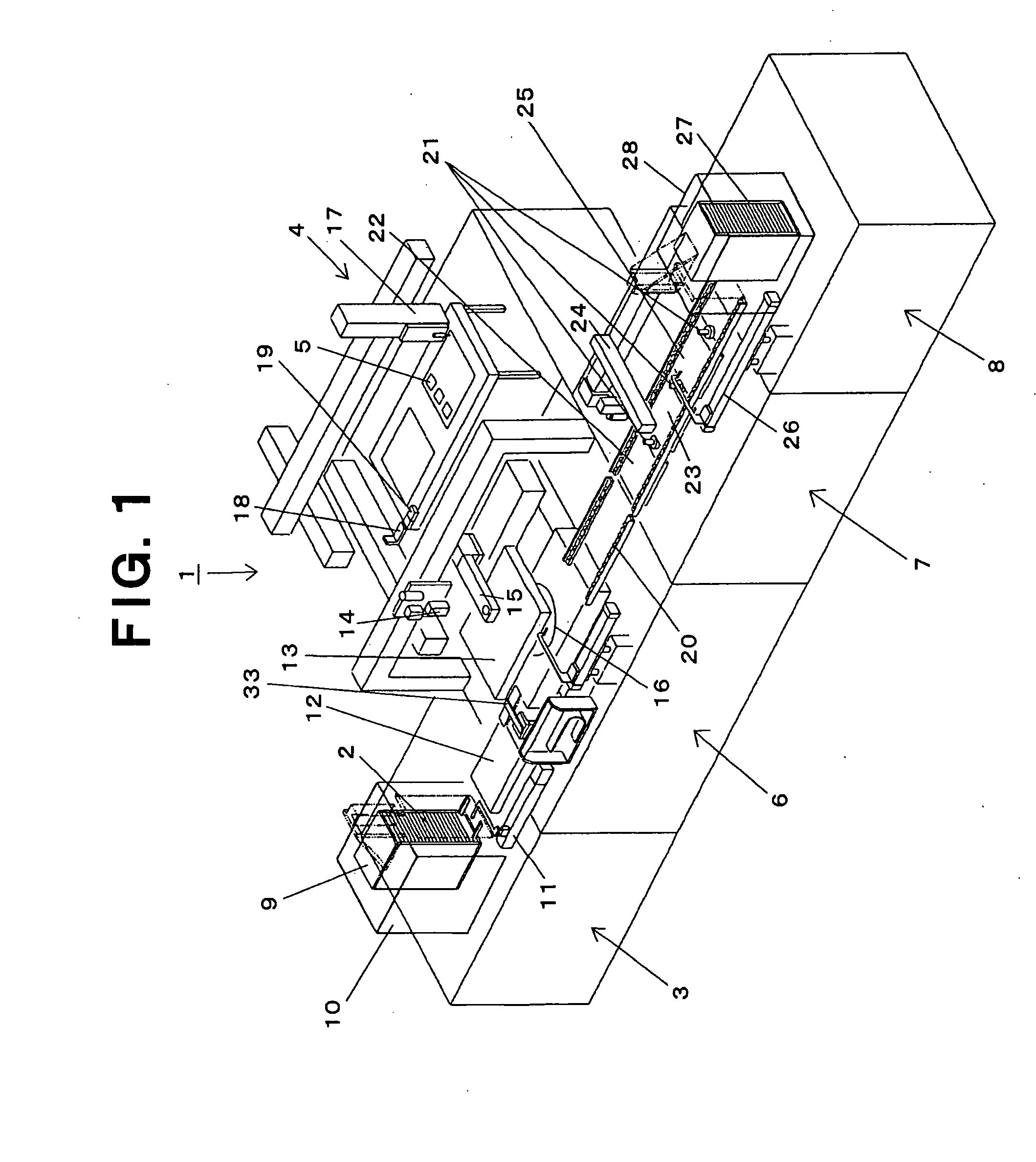
[0050]FIG. 1 shows a mounting system according to an embodiment of the present invention. In FIG. 1, symbol 1 shows the whole of a mounting system, and in this embodiment, mounting system 1 has a substrate loader section 3 for sequentially supplying substrates 2 to a chip mounting section 6, the chip mounting section 6 for mounting chips 5 sent from a chip loader section 4 onto substrates 2 supplied, a resin providing section (underfill section) 7 for providing a resin (underfill agent) between the substrate 2 and the chip 5 and curing the resin, and a substrate unloader section 8 for sequentially taking out the substrates 2, whereupon chips 5 are mounted, from the chip mounting section 6 (in this embodiment, from the underfill section 7).

[0051]In substrate loader section 3, an oven 10 is provided as a first oven capable of heat insulating substrate 2 together with a substrate ma...


PUM

PropertyMeasurementUnit
Temperatureaaaaaaaaaa
aaaaaaaaaa

Abstract

A mounting system is provided with a substrate loader section, a chip mounting section, and a substrate unloader section for sequentially taking out substrates whereupon chips are mounted. The mounting system is characterized in that the substrate loader section is provided with an oven capable of heat insulating a substrate together with a substrate magazine capable of containing a plurality of substrates, a stage heater for heating / heat insulating a substrate is provided, respectively, at a substrate conveying portion from a substrate waiting stage for the chip mounting section to the chip mounting section, at the chip mounting section, and at a substrate conveying portion from the chip mounting section to the substrate unloader section, and the substrate unloader section is provided with an oven capable of heat insulating a substrate together with a substrate magazine capable of containing a plurality of substrates whereupon chips are mounted. The substrate can be sustained at a desirable temperature over the substantially entire mounting process having a series of steps, and in particular, occurrence of problems ascribed to moisture absorption can be suppressed or prevented.

Description

TECHNICAL FIELD OF THE INVENTION[0001]The present invention relates to a mounting system for mounting a chip onto a substrate, and specifically, to a mounting system capable of carrying out a high-accuracy mounting under a stable temperature condition.BACKGROUND ART OF THE INVENTION[0002]In a process for mounting a chip onto a substrate, for example, in a process for mounting a semiconductor chip onto a resin-group multi-layer circuit board, it is desired to pay attention to problems accompanied with temperature variation of the substrate, particularly, problems ascribed to moisture absorption accompanied with the temperature variation. A substrate to be mounted with a chip is frequently served usually to a process wherein it is once baked in order to evaporate moisture before mounting, it is supplied to a substrate loader at a style of a substrate magazine containing a plurality of substrates, and it is supplied from the section of the substrate loader to a chip mounting section. I...

Claims


Application Information

Patent Timeline
IPC IPC(8): H01L21/00
CPCH01L21/563H01L21/67109H01L21/67144H01L24/75H01L24/81H01L2224/75Y10T29/41H01L2924/14H01L2924/01005H01L2924/01006H01L2924/01033H01L2924/01075H01L2924/01004H01L2924/15788H01L2924/00H01L21/48
Inventor MASUMOTO, MUTSUMITERADA, KATSUMI
Owner TORAY ENG CO LTD
Why Eureka
Try Eureka