
Ceramic matrix composite attachment apparatus and method

a technology of ceramic matrix composite and attachment apparatus, which is applied in the direction of machines/engines, stators, liquid fuel engines, etc., can solve the problems of affecting the design of durable mechanisms, weak inter-laminar tensile strength of ceramic matrix composite, and inability to meet the requirements of the application

Active Publication Date: 2009-01-08
SIEMENS ENERGY INC
View PDF5 Cites 84 Cited by
  • Summary
  • Abstract
  • Description
  • Claims
  • Application Information

AI Technical Summary

Problems solved by technology

However, CMC has relatively weak inter-laminar tensile strength, which can cause weakness at the base of a CMC flange, especially in the cyclical thermal and mechanical stresses of a gas turbine engine environment.
Thus, it has been problematic to design durable mechanisms for attaching CMC components to metal structures in gas turbines.

Method used


Image

  • Ceramic matrix composite attachment apparatus and method
  • Ceramic matrix composite attachment apparatus and method
  • Ceramic matrix composite attachment apparatus and method

Examples


Embodiment Construction

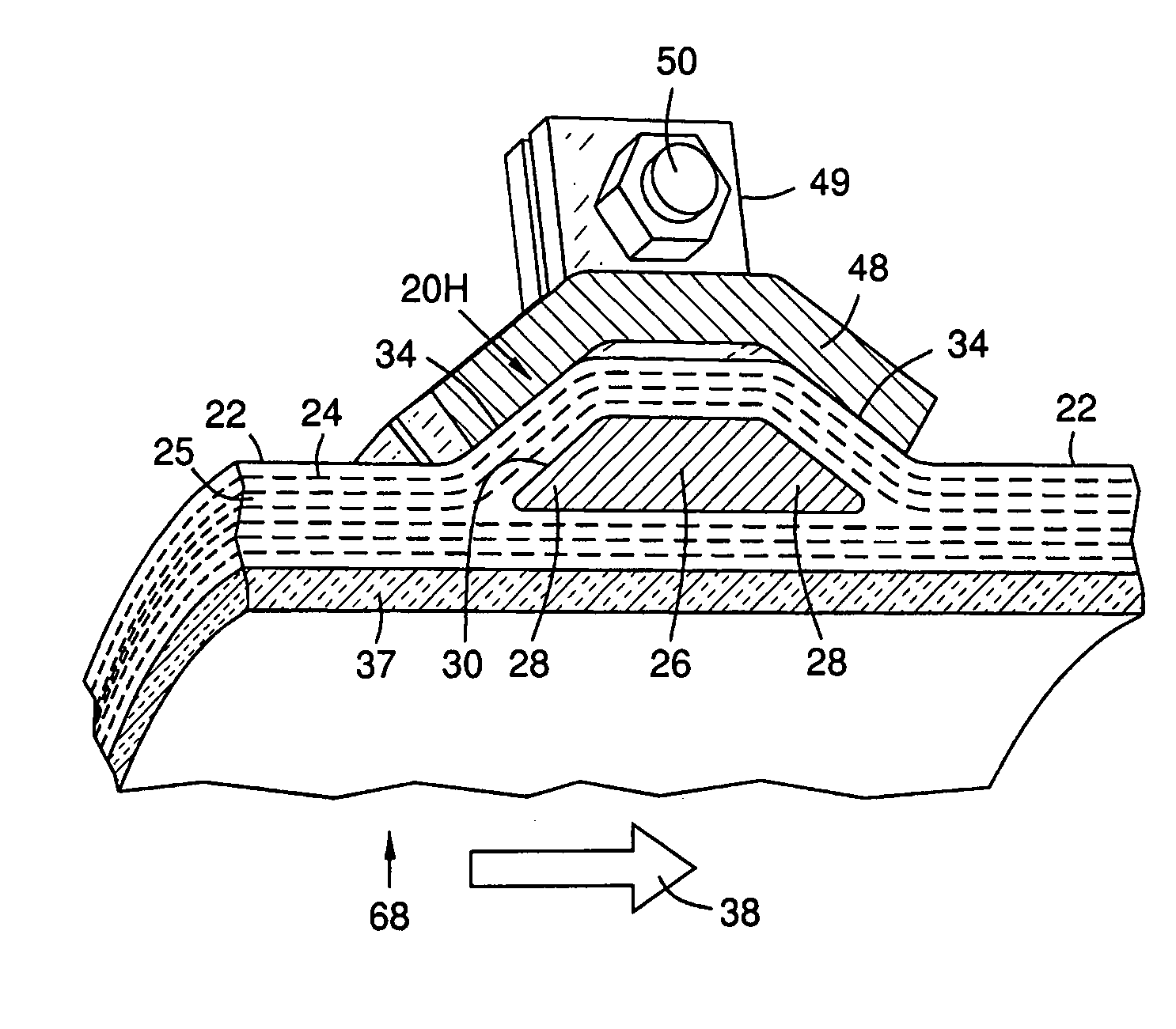
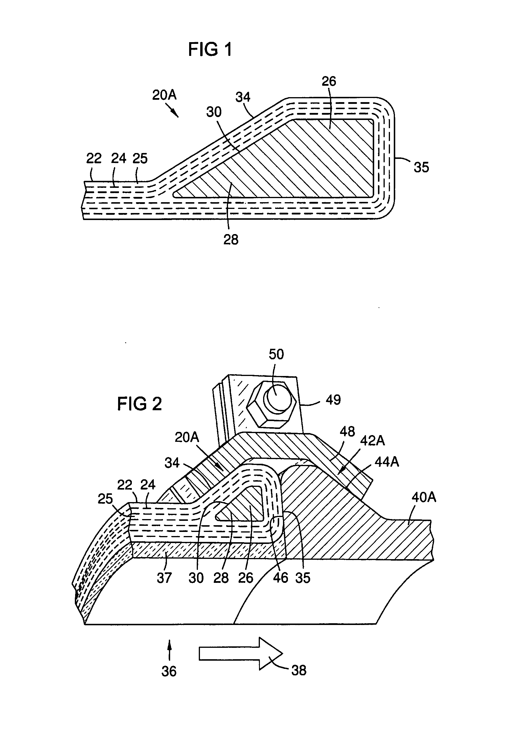
[0015]FIG. 1 shows a sectional view of a CMC flange 20A on an edge of a CMC wall structure 22. The wall structure is composed of one or more layers of CMC fabric 24, such as a ceramic or carbon fabric, impregnated with a ceramic matrix 25 as known in the art. A core block 26 of additional ceramic material with a generally wedge-shaped portion 28 is attached to the CMC wall structure 22. The block has an inner oblique surface 30 relative to the CMC wall structure, where “inner” means proximal to a geometric center of the CMC wall structure. The CMC fabric 24 is wrapped at least partly around the block 26, and is bonded to it. This forms the flange 20A with a solid core 26. The core may be a monolithic ceramic, or it may be built-up from layers of CMC fabric. The CMC fabric 24 of the wall structure may be formed continuously around the block 26 by means of 3-dimensional weaving as in FIG. 1, or it may be wrapped partially around the block in a lay-up process. The resulting flange 20A ...


PUM


Abstract

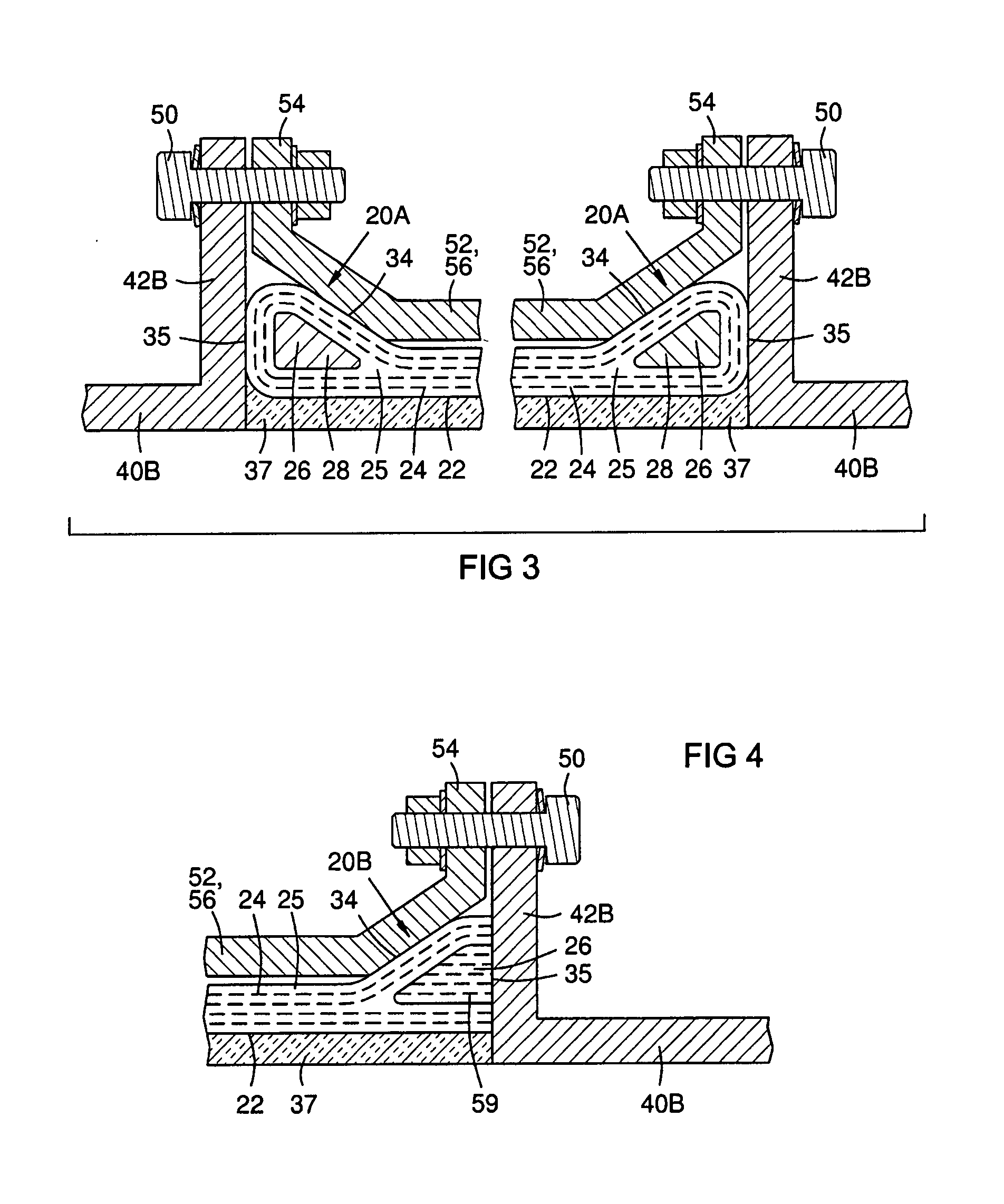
An attachment method and flange for connecting a ceramic matrix composite (CMC) component, such as a gas turbine shroud ring (36, 68), to a metal support structure. A CMC flange (20A) may be formed by attaching a wedge-shaped block (26) of a ceramic material to a CMC wall structure (22), and wrapping CMC layers (24) of the wall structure (22) at least partly around the block (26), forming the flange (20A) with an inner oblique face (34) and an outer face (35) normal to the wall structure. An adjacent support structure, such as a metal support ring (40A), may abut the outer face (35) of the CMC flange (20A) and be clamped or bolted to the CMC flange (20A).

Description

FIELD OF THE INVENTION[0001]This invention relates to Ceramic Matrix Composite (CMC) attachment methods and mechanisms, particularly for attaching CMC components such as shroud rings or combustor liners to metal support structures in a gas turbine.BACKGROUND OF THE INVENTION[0002]Gas turbine engines have rotating turbine blades surrounded by a shroud. Each circular array of blades on a rotating turbine disc is closely surrounded by a shroud ring, which may be a full hoop or assembled from arcuate segments. Engine efficiency is proportional to combustion temperature, so modern gas turbines use ceramics in these shroud rings and other components, since ceramics surpass metals in heat tolerance. Ceramic matrix composite (CMC) components are often used, and they must be attached to metal support structures.[0003]A flange is a common device for attaching components together with bolts, and flanges are often satisfactory for metal components. However, CMC has relatively weak inter-laminar...

Claims


Application Information

Patent Timeline
IPC IPC(8): F01D1/02
CPCF01D21/045F01D25/243F05D2300/603F05D2300/21F01D25/246
Inventor KELLER, DOUGLAS A.MORRISON, JAY A.
Owner SIEMENS ENERGY INC
Learn More