
Model-based control systems and methods for gas turbine engines

Inactive Publication Date: 2005-09-08
GENERAL ELECTRIC CO
View PDF99 Cites 182 Cited by
  • Summary
  • Abstract
  • Description
  • Claims
  • Application Information

AI Technical Summary

Benefits of technology

[0006] One embodiment of the invention relates to a method of controlling a gas turbine engine. The engine has sensors to detect one or more parameters and actuators adapted to respond to commands. The method includes receiving data from the sensors of the engine for one or more measured or sensed parameters, estimating a state of the engine by estimating one or more unmeasured or unsensed parameters using the data from the sensors and a predictive model of the engine, generating commands for the actuators based on the state using an optimization algorithm, and transmitting the commands to the engine.
[0007] Another embodiment of the

Problems solved by technology

Mechanical and electrical parts and / or systems can deteriorate, fail or be damaged.
Any component in a gas turbine system, including engine components, sensors, actuators, or any of the engine subsystems, is susceptible to degradation, failure or damage that causes the engine to move away from nominal conditions.
The effect that these upsets have on the gas turbine performance ranges from no effect (e.g., possibly due to a single failed sensor in a multi-sensor system) to a total loss of engine power or thrust control (e.g., for a failed actuator or damaged engine component).
Online engine health management is typically limited to sensor failure detection (e.g., range and rate checks), actuator position feedback errors, and some selected system anomaly checks, such as stall detection, rotor overspeed, and other such indications of loss of power or thrust control.
It is believed that presently no adequate adaptive model-based control systems and methods are available.

Method used


Image

  • Model-based control systems and methods for gas turbine engines
  • Model-based control systems and methods for gas turbine engines
  • Model-based control systems and methods for gas turbine engines

Examples


Embodiment Construction

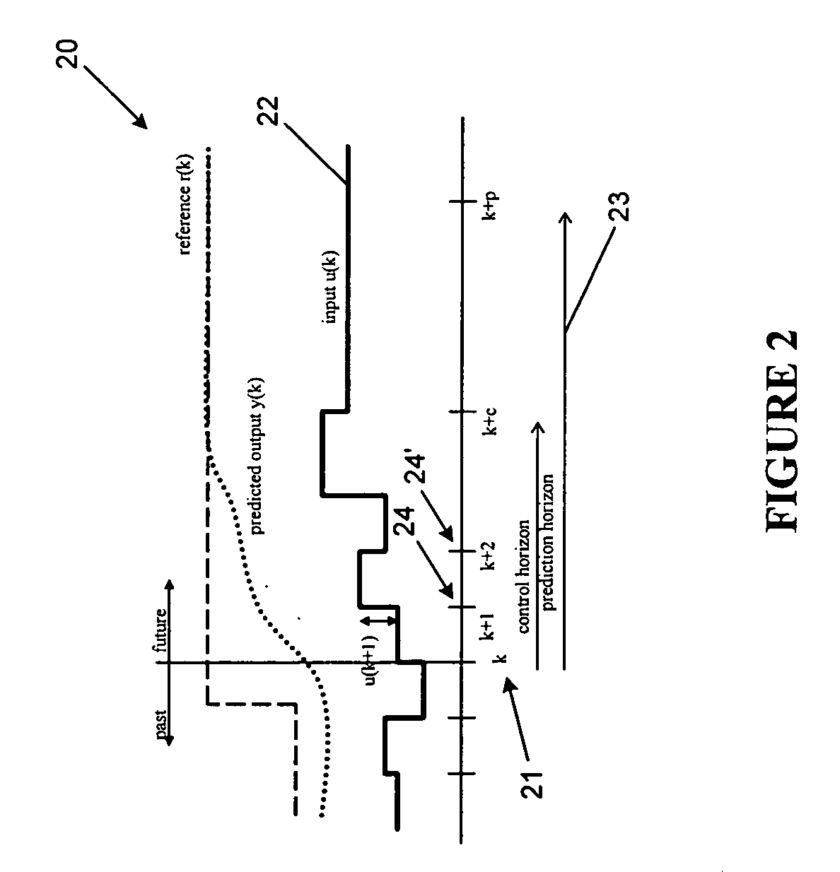
[0011] Embodiments of the present invention provide control systems and methods wherein the models, optimizations, objective functions, constraints and / or parameters in the control system modify, update and / or reconfigure themselves whenever any engine component or system moves away from nominal so that as much performance and / or operability as possible can be regained. Further, systems and methods according to embodiments of the present invention provide that the control system updates itself in real-time. The systems and methods may be automated using a computer. Embodiments of the present invention may take information about detected deterioration, faults, failures and damage and incorporate such information into the proper models, optimizations, objective functions, constraints and / or parameters in the control system to allow the control system to take optimized action given the current engine condition. Such systems and methods may allow any level of deterioration, faults, fail...


PUM


Abstract

A method and system of controlling a gas turbine engine is disclosed. The engine has sensors to detect one or more parameters and actuators adapted to respond to commands. The method includes receiving data from the sensors of the engine for one or more measured or sensed parameters, estimating a state of the engine by estimating one or more unmeasured or unsensed parameters using the data from the sensors and a predictive model of the engine, generating commands for the actuators based on the state using an optimization algorithm; and transmitting the commands to the engine. The system includes a state estimator adapted to estimate a state of the engine by estimating one or more unmeasured or unsensed parameters using data from the sensors of the engine for one or more measured or sensed parameters. The estimator includes a model of the engine. The system also includes a control module adapted to generate commands for the actuators based on the state. The control module includes an optimization algorithm for determining the commands.

Description

[0001] This invention was made with Government support under government contract no. F33615-98-C-2901 awarded by the U.S. Department of Defense to General Electric Corporation. The Government has certain rights in the invention, including a paid-up license and the right, in limited circumstances, to require the owner of any patent issuing in this invention to license others on reasonable terms.BACKGROUND OF THE INVENTION [0002] The present invention relates generally to systems and methods for controlling a gas turbine engine. More specifically, the present invention relates to adaptive model-based control systems and methods that maximize capability after deterioration, fault, failure or damage to one or more engine components or systems so that engine performance and / or operability can be optimized. [0003] Mechanical and electrical parts and / or systems can deteriorate, fail or be damaged. Any component in a gas turbine system, including engine components, sensors, actuators, or an...

Claims


Application Information

Patent Timeline
IPC IPC(8): F02C9/28F02C9/00G05B13/02G05B13/04
CPCG05B13/048G05B13/042
Inventor BRUNELL, BRENT JEROMEKUMAR, ADITYA
Owner GENERAL ELECTRIC CO
Learn More