
Thin film bulk and surface diffuser

a thin film and surface diffuser technology, applied in the field of optical displays, can solve the problems of increasing costs, deformation or warpage of plates, and undesirable illumination profiles,

Inactive Publication Date: 2009-01-08
SKC HAAS DISPLAY FILMS CO LTD
View PDF10 Cites 10 Cited by
  • Summary
  • Abstract
  • Description
  • Claims
  • Application Information

AI Technical Summary

Benefits of technology

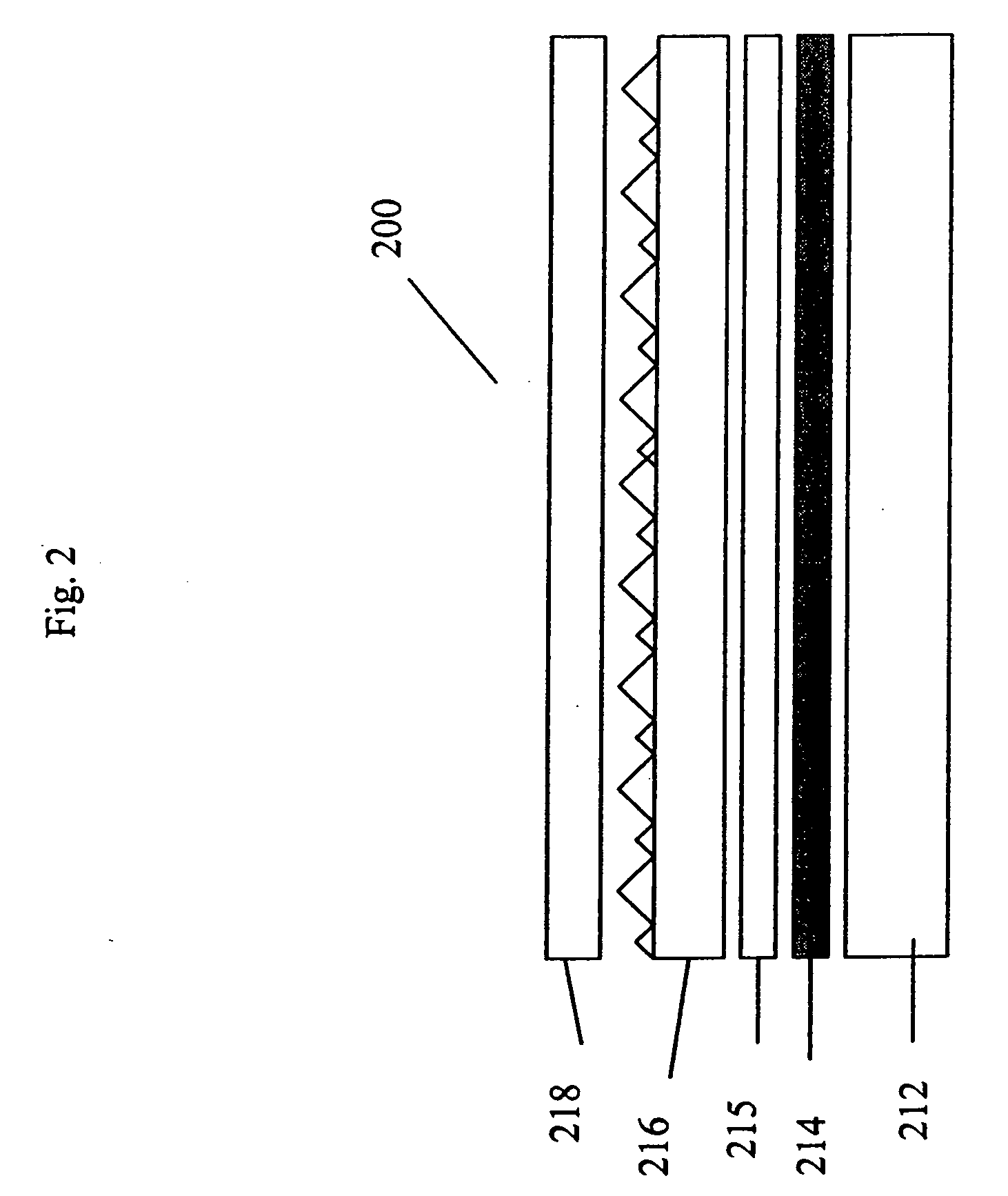
[0007]Desirably it has a shrinkage of less than 1% as a result of thermal changes from 0-90C. This film is useful in replacing the optical function of diffuser plates and top diffuser typically used today in backlit LCD displays.

Problems solved by technology

Such an illumination profile is not desirable, and so a diffuser plate is used to smooth the illumination profile at the back of the LCD device.
These plates often deform or warp after exposure to the elevated humidity and high temperature caused by the lamps.
In addition, the diffusion plates require customized extrusion compounding to distribute the diffusing particles uniformly throughout the polymer matrix, which further increases costs.
Although this solution is novel the need to use adhesives to laminate these layers together results in reduced efficiency of the system by adding light absorption materials.
Also the additional processing cost to laminate the layers together is self-defeating.
Also, this previous disclosure does not teach the materials and structure for an unattached diffuser film.
Producing a thin voided film that meets these requirements is very challenging as thin voided films are highly prone to shrinkage under elevated temperatures.

Method used


Image

  • Thin film bulk and surface diffuser
  • Thin film bulk and surface diffuser
  • Thin film bulk and surface diffuser

Examples


examples

[0055]Samples of voided polymeric optical diffuser films were prepared and coated with a dispersion of polymeric binder and beads and their performance in combination with an optically transmissive self-supporting substrate was compared to A sample of voided polymeric optical diffuser film.

Sample EX 1 (Control) Voided Diffuser without Beads

[0056]PET (#7352 from Eastman Chemicals) was dry blended with Polypropylene (“PP”, Huntsman P4G2Z-159) at 5% by weight and with a 1 part PET to 1 part TiO2 concentrate (PET 9663 E0002 from Eastman Chemicals) at 0.5% by weight. This blend was then dried in a desicant dryer at 65 C for 12 hours.

[0057]Cast sheets were extruded using a 2½″ extruder to extrude the PET / PP / TiO2 blend. The 275C meltstream was fed into a 7 inch film extrusion die also heated at 275 C. As the extruded sheet emerged from the die, it was cast onto a quenching roll set at 55C. The PP in the PET matrix dispersed into globules between 10 and 30 um in size during extrusion. The f...


PUM


Abstract

A voided semi-crystalline polymeric integrated optical diffuser film is provided with surface beads. The film is useful when incorporated into a display device such as an LC display.

Description

FIELD OF THE INVENTION[0001]The invention relates to optical displays, and more particularly to liquid crystal displays (LCDs) that may be used in LCD monitors and LCD televisions.BACKGROUND[0002]Liquid crystal displays (LCDs) are optical displays used in devices such as laptop computers, hand-held calculators, digital watches and televisions. Some LCDs include a light source that is located to the side of the display, with a light guide positioned to guide the light from the light source to the back of the LCD panel. Other LCDs, for example some LCD monitors and LCD televisions (LCD-TVs), are directly illuminated using a number of light sources positioned behind the LCD panel. This arrangement is increasingly common with larger displays, because the light power requirements, to achieve a certain level of display brightness, increase with the square of the display size, whereas the available real estate for locating light sources along the side of the display only increases linearly...

Claims


Application Information

Patent Timeline
IPC IPC(8): G02B6/02
CPCG02B5/0226G02B5/0247G02B5/0278G02F2001/133507G02F1/133504G02F1/133606G02B2207/107G02F1/133507G02B5/02G02F1/1335
Inventor LANEY, THOMAS M.AYLWARD, PETER T.RANKIN, JR., CHARLES M.
Owner SKC HAAS DISPLAY FILMS CO LTD
Learn More