
Electrode systems, devices and methods

a technology of electrodes and electrodes, applied in the field of electrode systems, devices and methods, can solve the problems of increasing medical care expenses, high labor costs, and time-consuming manual application of surface electrodes

Active Publication Date: 2009-01-01
UNIVERSITY OF PITTSBURGH
View PDF17 Cites 57 Cited by
  • Summary
  • Abstract
  • Description
  • Claims
  • Application Information

AI Technical Summary

Benefits of technology

[0050]The elongated contact member can, for example, have a specific operating impedance on skin of less than 50 kΩ*cm2, less than k20 Ω*cm2 or even less than k10 Ω*cm2.

Problems solved by technology

Affixing surface electrodes manually is time-consuming with a high labor cost, thereby increasing medical care expenses.
As the number of electrodes increases, which is desirable in, for example, certain EEG data analysis such as Laplacian mapping and source localization, manual placement of individual electrodes can become impractical, regardless of the cost.
However, EEG electrodes currently used in the clinical setting exhibit a number of problems related to both manual and automatic placement.
In automatic placement, however, such operations are difficult to perform.
Application of electrolyte gel to a large number of electrodes through an automatic system in a reproducible manner is also difficult.
In addition, the currently used gel has poor consistency and tends to spread, which could cause interference with neighboring electrodes, especially when high electrode density is required.
Further, currently used gels often dry completely in approximately 1 to 2 hours, which presents a problem when long term monitoring (for example, in certain EEG procedures) is desired.
Otherwise, pain and infection (resulting from over preparation) or high impedance (resulting under preparation) may result.
The depth of epidermal preparation is difficult to control automatically.
Attempts to reduce or eliminate such problems associated with standard surface electrodes have met with limited success.

Method used


Image

  • Electrode systems, devices and methods
  • Electrode systems, devices and methods
  • Electrode systems, devices and methods

Examples


Embodiment Construction

[0094]The present invention is discussed below in connection with representative examples of surface electrodes for contact with skin / tissue to measure biopotentials or biocurrents. However, one skilled in the art appreciates that the electrodes of the present invention can be used in a variety of manners (particularly were substantial electrode hydration is desirable). Moreover, one skilled in the art appreciates that electrodes of the present invention can also be used to apply a potential or current.

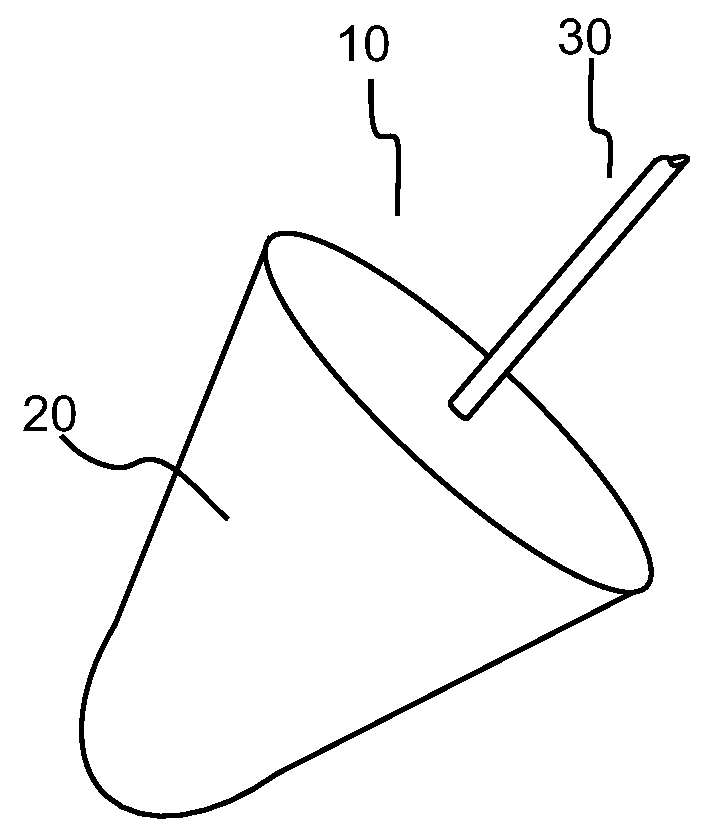
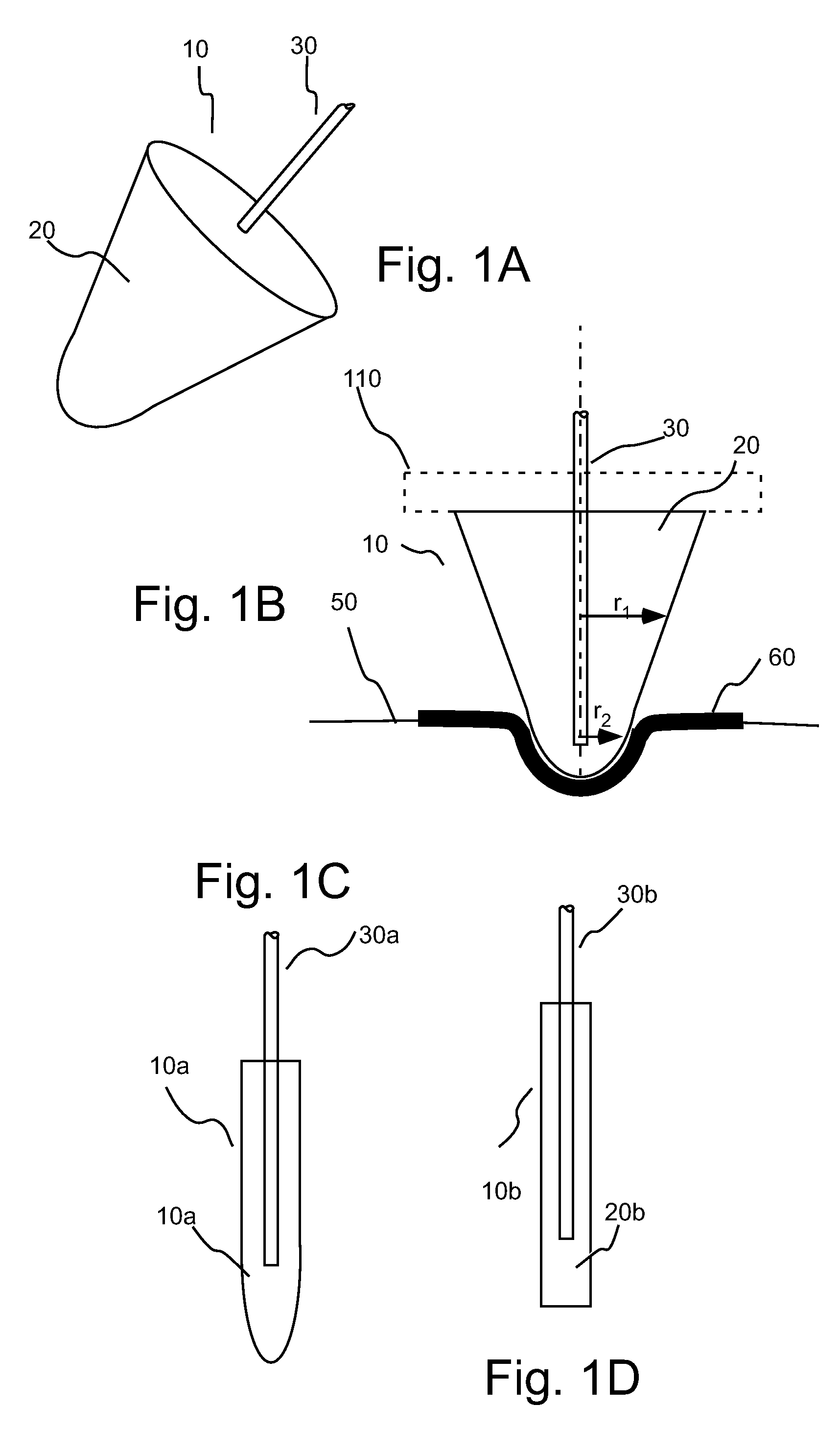
[0095]In several embodiments, the present invention provides surface electrodes such as skin surface electrode systems for measuring biopotential such as in EEG, ECG etc. In a number of embodiments, tissue contact portions, sections or elements of electrode systems of the present invention exhibit smaller specific impedance than electrodes currently used in, for example, EEG and ECG. As used herein, the terms “tissue contact element” or “skin contact element” refer to that portion of ...


PUM


Abstract

An electrode system include a flowable and cohesive surface contact element comprising a hydrophilic polymer swollen with an electrolyte fluid, the contact element having a Q′ ratio of at least 5 as defined by the equationQ′=WWWGwherein WG is the dry weight of the hydrophilic polymer and WW is weight of water in the sample after absorption of the electrolyte fluid comprising water and an electrolyte salt. The surface contact element can consist essentially of the hydrophilic polymer swollen by the electrolyte fluid. Another electrode system includes a contact element including a crosslinked hydrophilic polymer matrix. The contact element has a Q′ ratio of at least 5 as defined by the equationQ′=WWWG.The contact elements can also have a Q′ ratio of at least 6, at least 7, at least 10 or even at least 11.

Description

CROSS-REFERENCE TO RELATED APPLICATION[0001]This application claims benefit of U.S. Provisional Patent Application Ser. No. 60 / 937,497, the disclosure of which is incorporated herein by reference.BACKGROUND OF THE INVENTION[0002]The present invention relates to electrode systems, devices and methods and, particularly, to electrode systems, devices and methods for use in contact with tissue (for example, skin) for electrophysical measurement.[0003]Skin surface electrodes are important components in many medical diagnostic systems including, for example, electrocardiography (ECG), electromyography (EMG), and electroencephalography (EEG). In these systems, the electrode plays a critical role as a transducer converting physiological variables, such as those of the heart, muscles and brain, respectively, in ECG, EMG and EEG, to electrical potentials (sometime referred to as biopotentials). The measured potentials are then amplified and processed by an instrument, such as an electronic me...

Claims


Application Information

Patent Timeline
Patent Type & Authority Applications(United States)
IPC IPC(8): A61B5/04A61B5/296
CPCA61B5/04087A61B5/0478A61B5/0492A61B2562/125A61B5/04A61N1/0472A61N1/0484A61N1/0492A61N1/0496A61N1/0408A61B2562/0215A61B2562/0217A61B5/259A61B5/291A61B5/296
Inventor CUI, XINYANALBA, NICOLAS ALEXANDERSUN, MINGUI
Owner UNIVERSITY OF PITTSBURGH
Learn More