Method and Device for Manufacturing Bag with Clamping Device

a manufacturing device and zipper member technology, applied in the field of manufacturing methods and manufacturing devices for manufacturing bags with zipper members, can solve the problems of affecting the sealing effect of the tape, affecting the sealing effect, and affecting the product quality of the bag, so as to avoid the sealing defect of the tape

Active Publication Date: 2009-01-01
IDEMITSU UNITECH CO LTD
View PDF7 Cites 12 Cited by
  • Summary
  • Abstract
  • Description
  • Claims
  • Application Information

AI Technical Summary

Benefits of technology

[0012]A manufacturing method for a bag with zipper members according to an aspect of the invention includes: overlaying a bag film with a tape with a zipper member in which the zipper member is integrally formed on one surface side of a tape body of the tape such that the tape with the zipper member travels in a zipper member introducing groove formed in a circumferential direction of a rotary drum, the tape and the bag film moved by rotation of the rotary drum in the overlaid state; and continuously heat-sealing the tape with the zipper member to the bag film by a seal bar having a welding surface in a curved shape corresponding to a circumferential shape of the rotary drum. Heat applied by the seal bar to the tape with the zipper member can be avoided from transferring to the rotary drum.
[0033]According to the aspect of the invention, since at least the outer circumferential portion of the rotary drum is made of a heat-insulating material, as state above, the heat of the seal bar is utilized for heat sealing of the tape with the zipper member and the bag film, thereby avoiding a seal defect.

Problems solved by technology

In Patent Document 1, since the welding is conducted by intermittently sending the tapes and the bag films, its productivity is low.
In addition, difference in force applied on the tapes with the zipper members and the bag films often causes wrinkles in the welding portion.
Further, since the tape with the zipper member and the bag film are pressed between the separator and the seal bar, large resistance force is generated in peeling the bag with the zipper members from the separator, thereby causing a cut in an edge of the welding portion or a wrinkle.
In Patent Document 2, unlike Patent Document 1, since the bags with the zipper members are continuously manufactured, the problem of low productivity and the problem caused by the separator will not happen.

Method used


Image

  • Method and Device for Manufacturing Bag with Clamping Device
  • Method and Device for Manufacturing Bag with Clamping Device
  • Method and Device for Manufacturing Bag with Clamping Device

Examples


example 1

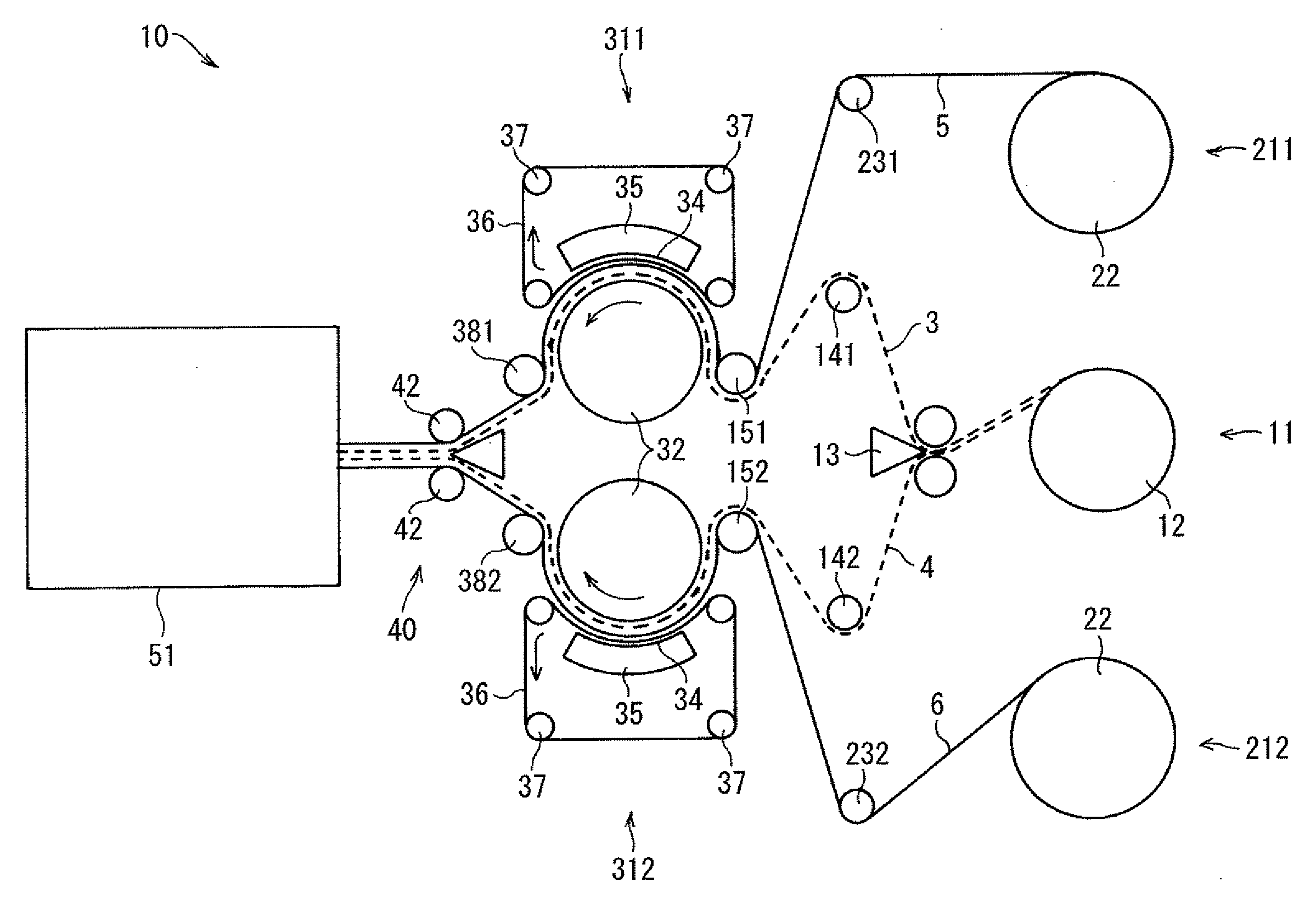
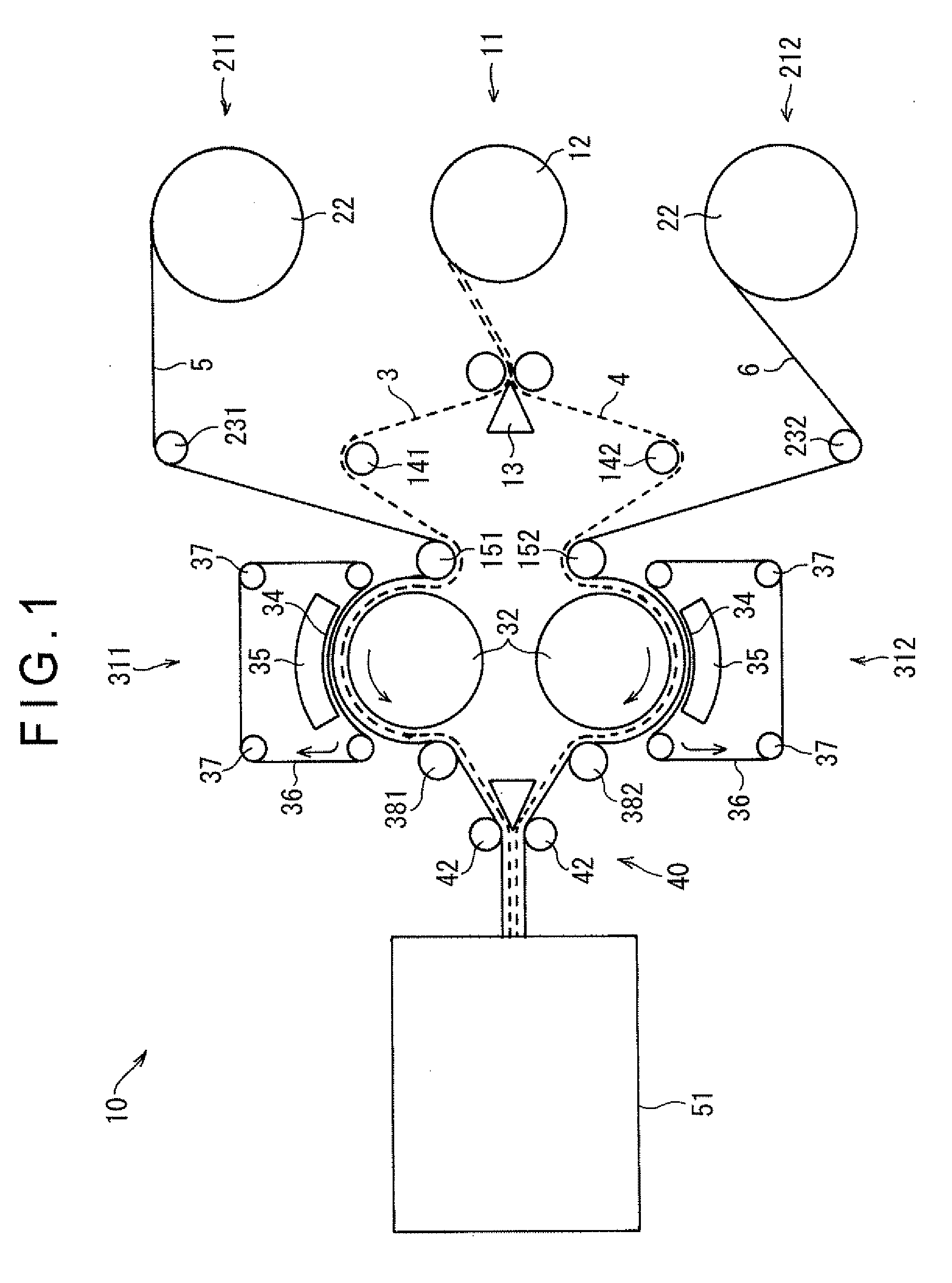
[0087]a) A bag with zipper members was manufactured using a laminate film as the bag film 5, 6 and a linear low-density polyethylene of which melting point is 120 degrees centigrade as the tape 3, 4 with the zipper member. The laminate film had an outer layer made of a biaxially oriented nylon and an inner layer made of a linear low-density polyethylene. Herein, the tape 3, 4 had a width of 7 mm.

b) The temperature of the seal bar 35 was about 150 degrees centigrade.

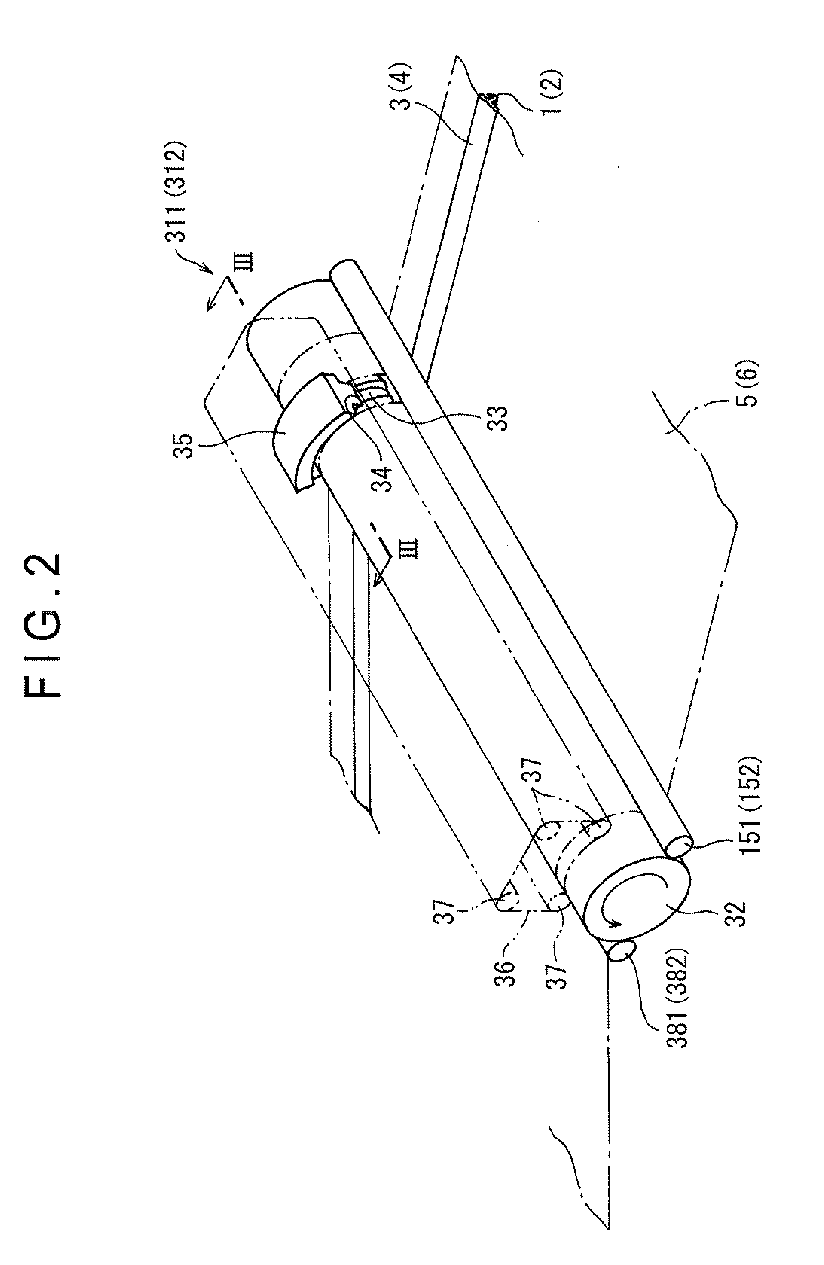
c) The tape introducing groove 33 for the tape with the zipper member had a shape shown in FIG. 3.

example 2

[0088]a), c)

[0089]However, the temperature of the seal bar 35 in b) is about 145 degrees centigrade. The tape 3, 4 with the zipper member has a structure shown in FIG. 5. The layer 3A, 4A of the tape body 31, 41 was made of metallocene LLDPE (Linear Low Density PolyEthylene) of which melting point is 95 degrees centigrade. The layer 3B, 4B was made of a linear low-density polyethylene of which melting point is 120 degrees centigrade.

example 3

[0090]a), c)

[0091]However, the temperature of the seal bar 35 in b) was about 125 degrees centigrade. The tape 3, 4 with the zipper member had a structure shown in FIG. 8. The convex portion 3D, 4D had a substantially triangle cross section. The height protruding from the layer 3B, 4B of the convex portion 3D, 4D was 0.3 mm. Two convex portions 3D, 4D were provided on sides in the longitudinal direction of the tape of the zipper members 1, 2. The layer 3A, 4A of the tape body 31, 41 was made of metallocene LLDPE of which melting point is 95 degrees centigrade. The layer 3B, 4B was made of a linear low-density polyethylene of which melting point is 120 degrees centigrade.


PUM


Abstract

A tape 3, 4 with a zipper member and a bag film 5,6 are continuously moved by rotation of a rotary drum 32 while being overlaid with each other such that the tape 3, 4 travels in a tape introducing groove 33 for a tape with a zipper member, the groove formed along a circumferential direction of the rotary drum 32. The tape 3, 4 with the zipper member is continuously welded to the bag film 5, 6 on a circumferential surface of the rotary drum 32 by a seal bar 35 that has a welding surface 34 in a curved shape corresponding to a circumferential surface shape of the rotary drum 32. The whole tape 3, 4 with the zipper member is accommodated in the tape introducing groove 33 for the tape with the zipper member and a seal surface of a tape body 31, 41 is adapted to be substantially flush with the circumferential surface of the rotary drum 32, so that heat applied from the seal bar 35 to the tape 3, 4 with the zipper member is restrained from transferring to the rotary drum 32.

Description

TECHNICAL FIELD[0001]The present invention relates to a manufacturing method and manufacturing device for manufacturing a bag with a zipper member made of a bag film on which a tape with a zipper member is welded, a zipper member integrally formed on one surface side of a tape body of the tape.BACKGROUND ART[0002]A reclosable bag that is a bag openable and closable by belt-like zipper members (an engaging unit) of a male and a female, the zipper members provided to an opening / closing portion of the bag, has been used for many fields such as food, medical products and miscellaneous goods.[0003]In manufacturing such a bag with the zipper members, a method has been known in which the zipper members are formed by extrusion molding while being welded to a surface of the bag film. However, the method contains a limitation on flexibility in combination of the zipper members and the bag film since the zipper members are welded at the same time as the molding. In addition, the molding of the...

Claims


Application Information

Patent Timeline
Patent Type & Authority Applications(United States)
IPC IPC(8): B31B1/90B31B50/64
CPCB31B19/90Y10S493/927B31B2219/9019B31B70/00B31B70/8132B31B2160/10B31B50/81
Inventor GOTO, SHUICHITANAKA, KENICHI
Owner IDEMITSU UNITECH CO LTD
Why Eureka
Try Eureka