
Information recording system and an information recording method

a technology of information recording system and information recording method, which is applied in the direction of recording signal processing, digital signal error detection/correction, instruments, etc., can solve the problems of limited pre-information signal ssub>pl/sub> output with poor precision, and insufficient suppression of noise signals derived,

Inactive Publication Date: 2009-01-01
PANASONIC SEMICON SOLUTIONS CO LTD
View PDF3 Cites 2 Cited by
  • Summary
  • Abstract
  • Description
  • Claims
  • Application Information

AI Technical Summary

Benefits of technology

[0017]Since the push-pull signal is thus corrected using the displacement threshold which depends on the amplitude of the push-pull signal, noise signals are sufficiently suppressed to obtain a precise corrected push-pull signal even when the amplitude of the push-pull signal is small. Consequently, a reference clock signal is generated based on the precise corrected push-pull signal, and information is precisely recorded on an optical disc using the reference clock signal.
[0003]The present invention relates to an information recording system and information recording method for recording information on an optical disc, and particularly to the technique of precisely generating a reference clock signal for use in, for example, precisely determining a recording position when recording information on a wobbled optical disc such as a DVD-R.

Problems solved by technology

When the amplitude of SPP is smaller, the limit signal accordingly has an increased proportion of width to amplitude, resulting in insufficient suppression of noise signals derived from various factors such as pre-pits.
Limited pre-information signal SPL is thus outputted with poor precision.
Since information recording systems record information using a reference clock generated based on limited pre-information signal SPL, deterioration in the precision of the limited pre-information signal SPL causes deterioration in, for example, recording quality.

Method used


Image

  • Information recording system and an information recording method
  • Information recording system and an information recording method
  • Information recording system and an information recording method

Examples


first embodiment

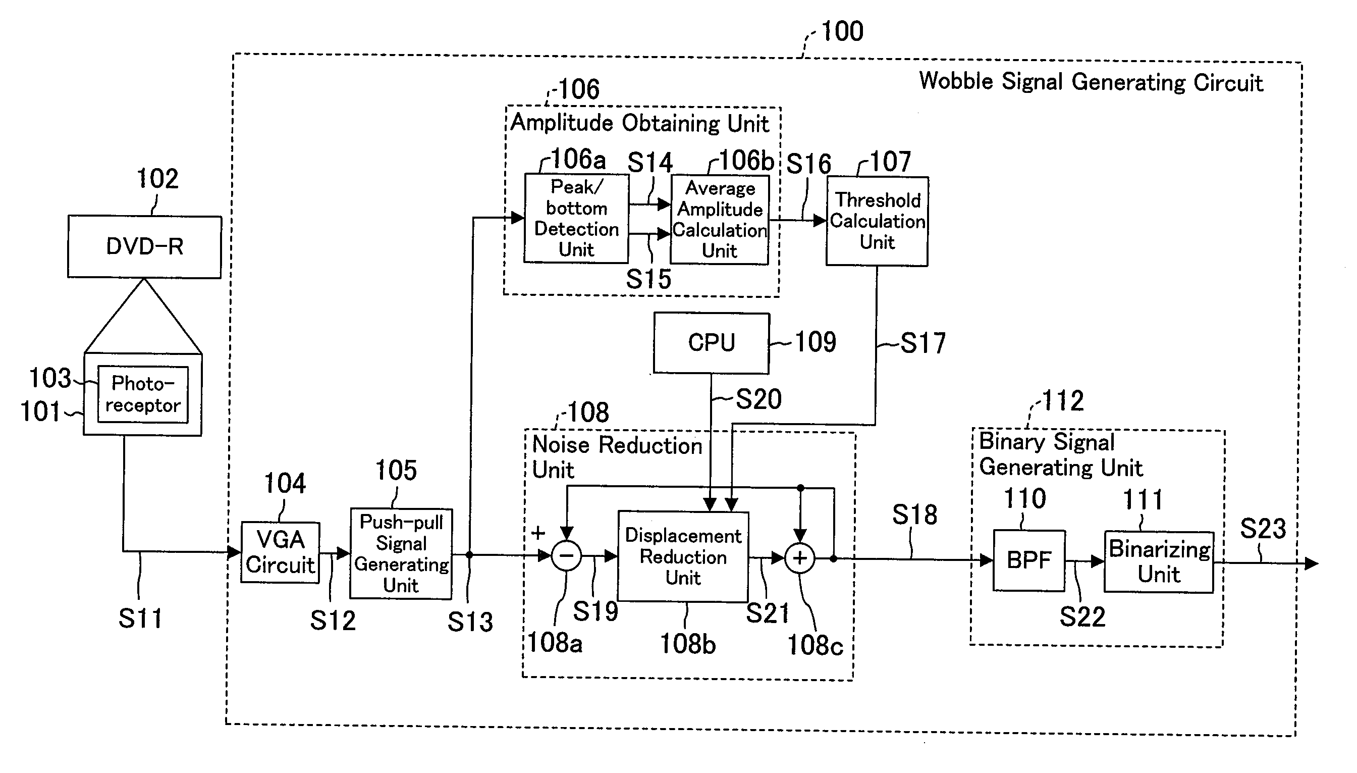
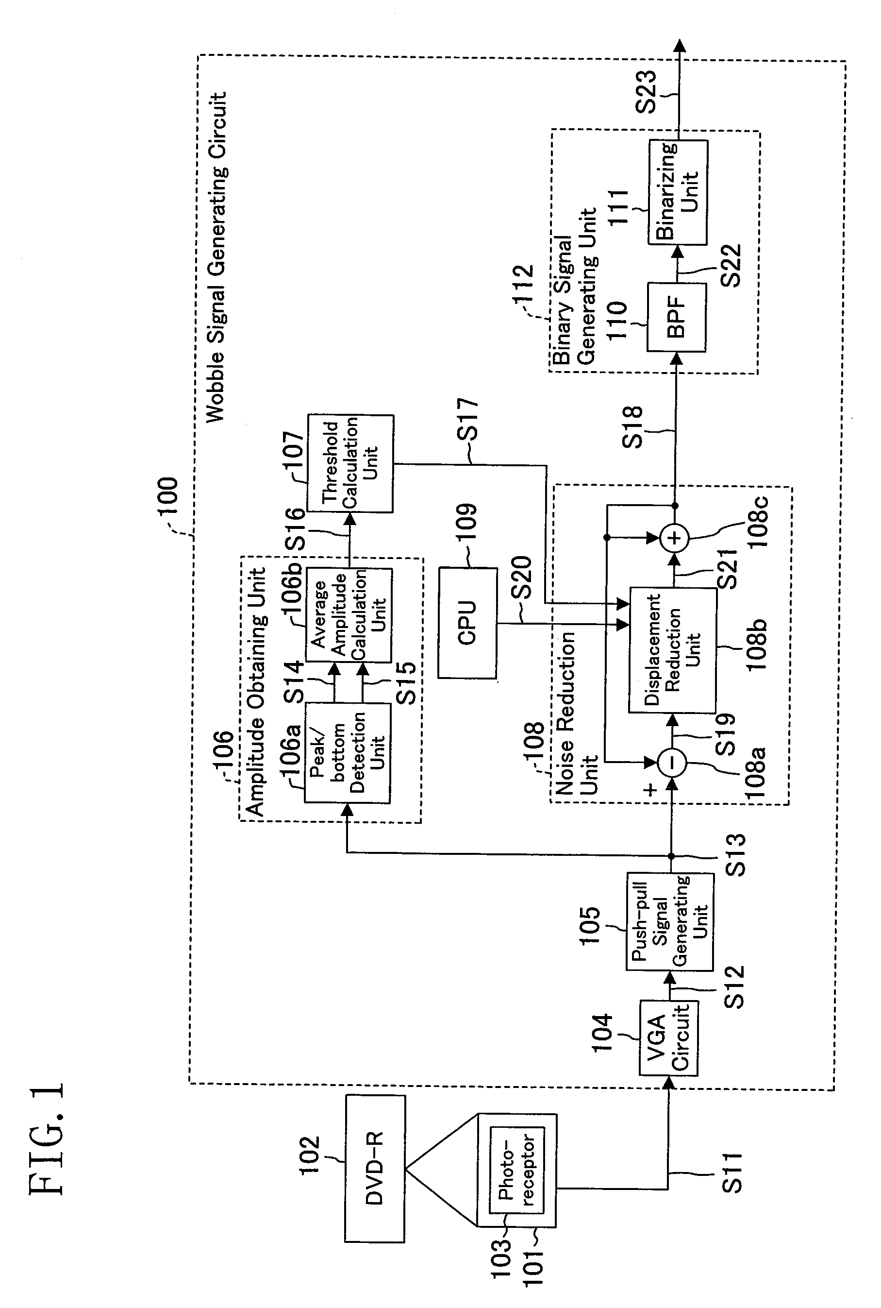
[0028]An information recording and reproducing system (an information recording system) according to the first embodiment of the present invention includes, as shown in FIG. 1, a wobble signal generating circuit 100 and an optical pickup 101, and records information on a DVD-R 102, which is a WO (Write Once) information recording medium accepting addition of writing but not accepting overwriting. The DVD-R 102 is formed with a recording surface having a spiral or concentric-circle recording area which is meandering, and the meandering is known as wobble.

[0029]The information recording and reproducing system of each embodiment herein detects a wobble frequency of an information track, e.g., a groove track, wobbled in the DVD-R 102 to generate (extract) a reference clock, based on the wobble frequency, for controlling the DVD-R 102 in rotation and recording. Information is recorded on the DVD-R 102 by controlling the DVD-R 102 in rotation and recording using the generated reference cl...

second embodiment

[0055]An information recording and reproducing system according to the second embodiment of the present invention includes a wobble signal generating circuit 200 instead of the wobble signal generating circuit 100 of the first embodiment, as shown in FIG. 5.

[0056]The wobble signal generating circuit 200 includes a track following detection unit 201 and a switching unit 202 in addition to the structure of the wobble signal generating circuit 100 of the first embodiment.

[0057]The track following detection unit 201 compares a tracking error signal to a predetermined threshold and determines that the information recording and reproducing system is in a track following mode when the tracking error signal is lower than the predetermined threshold and determines that the system is not in the track following mode when the tracking error signal is not less than the predetermined threshold. A track following mode is a mode in which a light beam is spotted on the track where the information is...

third embodiment

[0061]An information recording and reproducing system according to the third embodiment of the present invention includes a wobble signal generating circuit 300 instead of the wobble signal generating circuit 100 of the first embodiment, as shown in FIG. 6.

[0062]The wobble signal generating circuit 300 includes a switching unit 202, a wobble frequency / phase following detection unit 301, and a PLL control unit 302 in addition to the structure of the wobble signal generating circuit 100 of the first embodiment.

[0063]The wobble frequency / phase following detection unit 301 determines whether the information recording and reproducing system is in a wobble frequency / phase following mode based on the frequency difference and the phase difference between wobble clock signal S26 generated by the PLL control unit 302 (described later) and wobble binary signal S23 outputted by the binarizing unit 111. When both the frequency and phase differences are not less than respective predetermined valu...


PUM

PropertyMeasurementUnit
wobble frequencyaaaaaaaaaa
threshold calculationaaaaaaaaaa
displacement thresholdaaaaaaaaaa

Abstract

An information recording system for recording information on an optical disc using a reference clock signal generated based on a push-pull signal including a wobble frequency component, the system includes an amplitude obtaining unit for obtaining an amplitude value of the push-pull signal, a threshold calculation unit for calculating a displacement threshold of the push-pull signal based on the amplitude value obtained by the amplitude obtaining unit, and a noise reduction unit for generating a corrected push-pull signal by correcting the push-pull signal such that a displacement exceeding the displacement threshold is reduced. The reference clock signal is generated based on the corrected push-pull signal generated by the noise reduction unit.

Description

CROSS-REFERENCE TO RELATED APPLICATIONS[0001]This application claims priority under 35 U.S.C. §119(a) on Japanese Patent Application No 2007-172645 filed on Jun. 29, 2007, the entire contents of which are hereby incorporated by reference.BACKGROUND OF THE INVENTION[0002]1. Field of the Invention[0003]The present invention relates to an information recording system and information recording method for recording information on an optical disc, and particularly to the technique of precisely generating a reference clock signal for use in, for example, precisely determining a recording position when recording information on a wobbled optical disc such as a DVD-R.[0004]2. Description of the Prior Art[0005]When recording data on a DVD-R, information recording systems detect a push-pull signal including a wobble frequency component of an information track by applying a light beam to the information track. Part of the light beam happens to be applied to pre-pits on tracks adjacent to the inf...

Claims


Application Information

Patent Timeline
Patent Type & Authority Applications(United States)
IPC IPC(8): G11B7/00
CPCG11B20/10009G11B20/1403G11B2220/2566G11B2220/218G11B27/24
Inventor OKUMURA, TOMOAKIHIRAKI, TSUYOSHIKOMAWAKI, KOUICHITANAKA, KIYOTAKATARUTANI, KAZUMASA
Owner PANASONIC SEMICON SOLUTIONS CO LTD
Learn More