
Wire TV system noise suppression device

A system noise and suppression device technology, applied in TV systems, TVs, electrical components and other directions adapted to optical transmission, can solve problems such as the malfunction of the return laser, the failure of normal communication in the CMTS access network, and the OBI interference of optical links. achieve the effect of suppressing noise signals

Inactive Publication Date: 2018-08-07
杭州万隆光电设备股份有限公司
View PDF6 Cites 0 Cited by
  • Summary
  • Abstract
  • Description
  • Claims
  • Application Information

AI Technical Summary

Problems solved by technology

[0003] The noise signal intruded from the TV port connected to the TV is output to the "uplink amplifier circuit" through the "passive splitter" and "duplex filter", and then amplified together with the uplink return signal sent by the CM, and then passed through the uplink optical The link is transmitted to the CMTS central equipment in the front-end computer room, which eventually leads to the deterioration of the carrier-to-noise ratio index of the uplink optical link, and even the entire system cannot pass normally.
[0004] If the entire optical link adopts the RFOG networking mode; then, the intrusive noise signal converged from the TV port connected to the TV may cause the malfunction of the backhaul laser, resulting in serious OBI of the entire RFOG uplink optical link Interference, eventually causing the entire CMTS access network to fail to communicate normally

Method used


Image

  • Wire TV system noise suppression device

Examples


Embodiment Construction

[0016] The technical solutions of the embodiments of the present invention will be explained and described below in conjunction with the drawings of the embodiments of the present invention, but the following embodiments are only preferred embodiments of the present invention, not all of them. Based on the examples in the implementation manners, other examples obtained by those skilled in the art without making creative efforts all belong to the protection scope of the present invention.

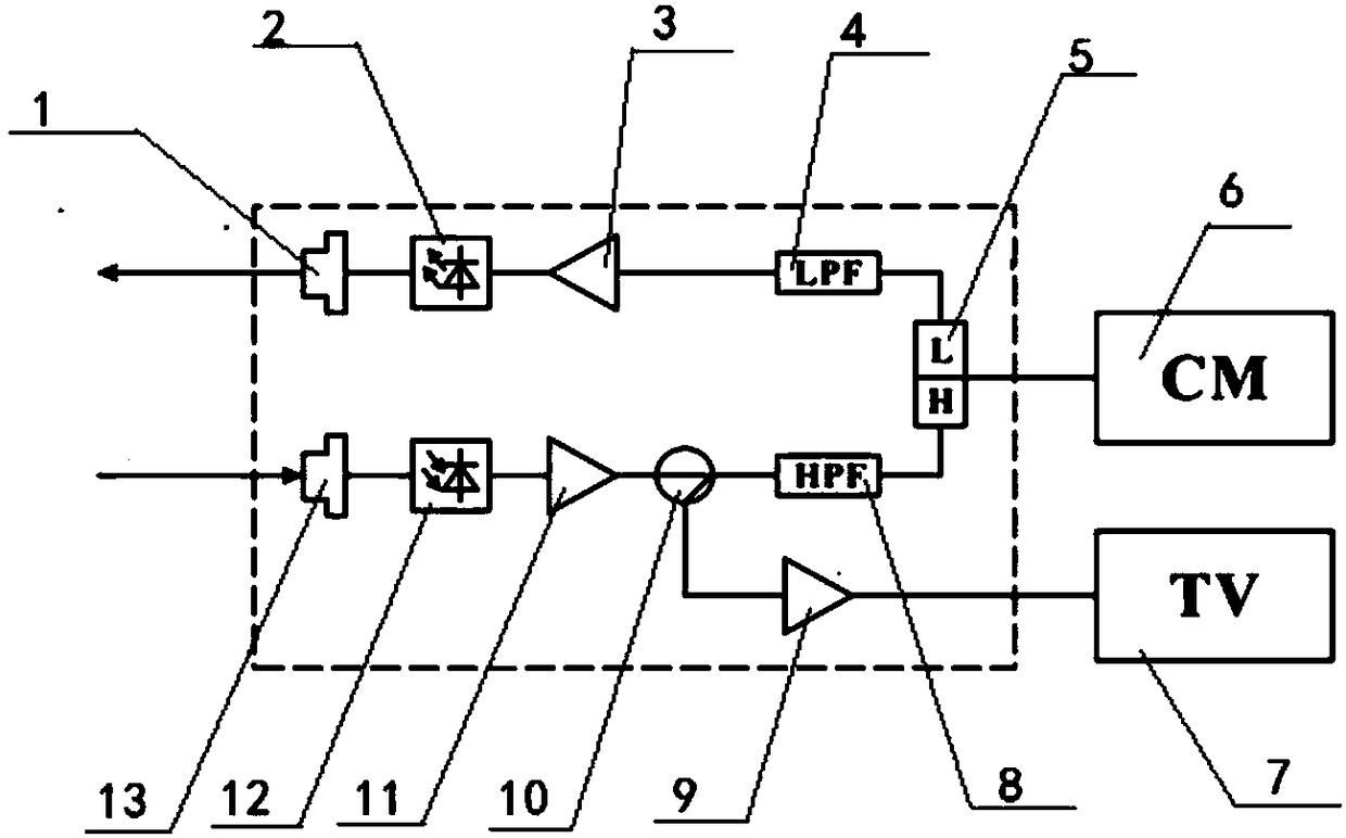
[0017] refer to figure 1 A kind of cable TV system noise suppressing device shown, comprises the DATA port 6 that is used to connect cable modem (CM), and DATA port 6 is respectively connected with uplink amplifying circuit 3 and first downlink amplifier 11 through duplex filter 5, The uplink amplifying circuit 3 is connected to the uplink optical signal terminal 1 through the first optical detector 2, the first downlink amplifier 11 is connected to the downlink optical signal terminal 13 th...


PUM


Abstract

The invention discloses a wire TV system noise suppression device, and belongs to the field of the photo-electricity. The wire TV system noise suppression device comprises a DATA port for connecting acable modem, the DATA port is respectively connected with an uplink amplifier circuit and a first downlink amplifier through a duplex filter, the uplink amplifier circuit is connected with an uplinkoptical signal end through a first optical detector, the first downlink amplifier is connected with a downlink signal end through a second optical detector, and a low-pass filter is connected betweenthe uplink amplifier circuit and the duplex filter.

Description

【Technical field】 [0001] The invention relates to a noise suppressing device for a cable TV system. 【Background technique】 [0002] Existing R-ONU access terminals usually have two output ports, one port is a "TV port" for connecting to a TV, and the other port is a "DATA port" for connecting to a cable modem (CM). [0003] The noise signal intruded from the TV port connected to the TV is output to the "uplink amplifier circuit" through the "passive splitter" and "duplex filter", and then amplified together with the uplink return signal sent by the CM, and then passed through the uplink optical The link is transmitted to the CMTS central office equipment in the front-end computer room, which eventually leads to the degradation of the carrier-to-noise ratio index of the uplink optical link, and even the entire system cannot pass normally. [0004] If the entire optical link adopts the RFOG networking mode; then, the intrusive noise signal converged from the TV port connected...

Claims


Application Information

Patent Timeline
Patent Type & Authority Applications(China)
IPC IPC(8): H04N7/10H04N7/22
CPCH04N7/102H04N7/22
Inventor 许泉海朱国堂余兴洪
Owner 杭州万隆光电设备股份有限公司
Learn More