Liquid ejecting head and liquid ejecting apparatus

a liquid ejector and liquid ejector technology, applied in printing and other directions, can solve the problems of insufficient space for ink-supply-needled surfaces, inability to detect dots, and inability to print accurately, so as to reduce the size of liquid-supply members, increase the area size of filters, and reduce dynamic pressure

Inactive Publication Date: 2009-01-01
SEIKO EPSON CORP
View PDF2 Cites 6 Cited by
  • Summary
  • Abstract
  • Description
  • Claims
  • Application Information

AI Technical Summary

Benefits of technology

[0013]If the configuration of a liquid ejecting head according to the aspects of the invention described above, it is possible to reduce the size of the liquid-supply member. In addition, it is possible to increase the area size of filters. As a result thereof, it is possible to decrease dynamic pressure. Since it is possible to decrease dynamic pressure, it is further possible to decrease a driving voltage that is applied to the means for generating pressure. Moreover, it is possible to make the lengths of the liquid-supply passages uniform, thereby preventing any variation or differences in the performance of the liquid-supply among the plurality of liquid-supply passages. Therefore, it is possible to achieve uniform liquid-discharging performance.
[0014]Furthermore, using the separate configuration of the liquid-supply member, which is made up of at least a first separate member and second separate member where the filters are adhered to the surface, it is possible to prevent the filters from being damaged, deformed, or even broken due to stress or pressure that is applied to the filters when the filters are adhered to the surface of the first separate member and second separate member. Moreover, it is possible to normalize the filtering characteristics, such as, pressure losses and / or air-trapping performance of these filter chambers substantially equal to one another regardless of the filtering positions across the liquid-supply passages.

Problems solved by technology

One difficulty with air bubbles in the ink cartridge is that the air bubbles may then be transferred to the ink supply from the ink cartridge to the ink ejection head body of the ink-jet recording head, where any entrapped air bubbles may adversely affect the print quality of the ink-jet recording head.
For example, problems with the ink discharge may result in missing dots, or other noticeable errors.
In addition, the ink-supply-needled-mounted surface needs enough space to form a margin or space between the ink-supply needles and filters.
Because these space requirements, it is not possible to reduce the space between adjacent ink-supply needles.
As another disadvantage of ink-jet recording heads of the related art is that the dynamic pressure increases as the area of the filters is reduced so as to make the head smaller.
One disadvantageous aspect of this configuration, however, is that some filters are adhered to one surface of the ink-supply head member after the other filters are adhered to the other surface of the ink-supply head member, causing a stress to be applied to the filters that are first adhered to the ink-supply head member.
Applying this stress to the filters may damage the filters.
For example, the filters may be deformed or even broken due to the stress.
Such differences among the shapes and characteristics of the filter chambers may cause pressure losses and / or differences in air-trapping performance from one filter chamber to another.

Method used


Image

  • Liquid ejecting head and liquid ejecting apparatus
  • Liquid ejecting head and liquid ejecting apparatus
  • Liquid ejecting head and liquid ejecting apparatus

Examples


embodiment 1

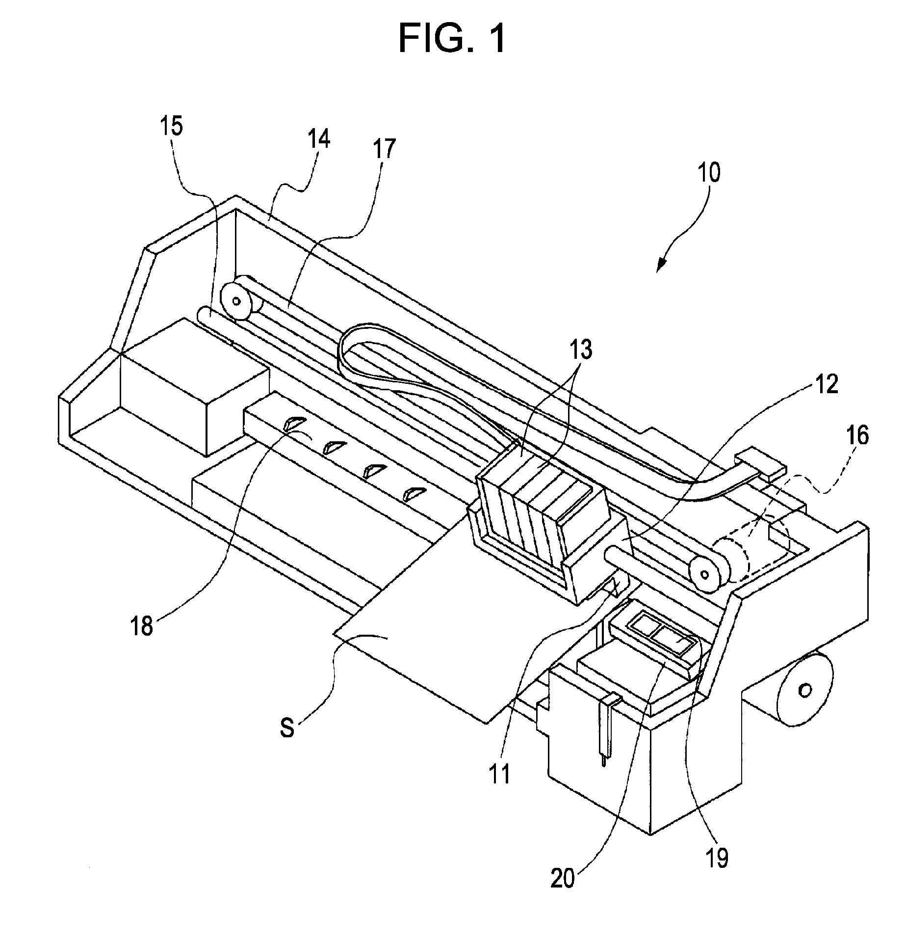
[0029]FIG. 1 is a perspective view that schematically illustrates an example of the configuration of an ink-jet recording apparatus, which is a non-limiting example of a liquid ejecting apparatuses according to a first exemplary embodiment of the invention. As illustrated in FIG. 1, the ink-jet recording apparatus 10 according to the present embodiment of the invention is provided with an ink-jet recording head 11 that is capable of discharging ink drops. The ink-jet recording head 11 is an example of a liquid ejecting head according to an aspect of the invention. The ink-jet recording apparatus 10 is further provided with a carriage 12. The ink-jet recording head 11 is fixed to the bottom of the carriage 12. Ink cartridges 13, each of which constitutes a non-limiting example of a liquid container capable of storing a liquid, are detachably attached to the ink-jet recording head 11. Each of these ink cartridges 13 contains ink which corresponds to one of a set of ink colors, for exa...


PUM


Abstract

The invention relates to a liquid ejecting head that includes a liquid ejecting head body, a liquid-supply member, and a plurality of filters. The liquid-supply member has a plurality of liquid-supply passages formed inside the liquid-supply member used for communicating the liquid to the liquid ejecting head body. The liquid-supply member includes a first and second separate member which are adhered to each other so as to make up the liquid-supply member. A plurality of first and second filters are provided across the plurality of liquid-supply passages. The plurality of liquid-supply passages includes first liquid-supply passages that have the first filters on the surface of the first separate member and second liquid-supply passages that have the second filters on the surface of the second separate member.

Description

[0001]The entire disclosure of Japanese Patent Application No. 2007-168807, filed Jun. 27, 2007 and Japanese Patent Application No. 2008-054156, filed Mar. 4, 2008 are expressly incorporated herein by reference.BACKGROUND OF THE INVENTION[0002]1. Technical Field[0003]The present invention generally relates to a liquid ejecting head capable of ejecting liquid from a plurality of nozzle openings formed in the surface of the liquid ejecting head. More specifically, the present invention relates to a liquid ejecting head comprising a liquid-retaining unit or container.[0004]2. Related Art[0005]Ink-jet recording heads are one example of variety of liquid ejecting heads that are widely used today. Typically, within the liquid ejecting heads, an ink-retaining unit or ink container supplies the ink to the ink ejection head body of the ink-jet recording head. For example, one non-limiting example of such an ink-containing unit is an ink cartridge. The recording heads operate by using a means...

Claims


Application Information

Patent Timeline
Patent Type & Authority Applications(United States)
IPC IPC(8): B41J2/175
CPCB41J2/17563
Inventor IMAI, ATSUSHIOWAKI, HIROSHIGE
Owner SEIKO EPSON CORP
Why Eureka
Try Eureka