
Spread Spectrum Software Receiver

a software receiver and spread spectrum technology, applied in satellite radio beaconing, measurement devices, instruments, etc., can solve the problems of software receiver implementations that are associated with one important drawback in comparison with corresponding hardware designs, and are generally not able to receive and process signals from sources belonging to a different system. , to achieve the effect of high power efficiency

Inactive Publication Date: 2009-01-01
QUALCOMM TECH INT
View PDF1 Cites 15 Cited by
  • Summary
  • Abstract
  • Description
  • Claims
  • Application Information

AI Technical Summary

Benefits of technology

[0009]The object of the present invention is therefore to alleviate the above problems and to provide

Problems solved by technology

Unfortunately, the dissimilarities in the frequency bands, and especially the signal formats used in the different systems, result in the situation that a signal receiver adapted for one system is generally not able to receive and process signals from sources belonging to a different system.
Including more than one receiver chain in a single device renders the device expensive, bulky and / or heavy.
However, software receiver implementations are associated with one important drawback in comparison with corresponding hardware designs.
Namely, a software implementation running on a generic microprocessor is typically less energy efficient (in terms of energy or power per output data) than one running on a dedicated hardware implementation, e.g. represented by an ASIC (Application Specific Integrated Circuit).
It is then predicted whether these resources are sufficient for the selected mode, and if it is estimated that the resources are insufficient, the operation of the device is restricted with respect to at least one operational mode.
However, besides this redundancy measure, no quality-related parameter influences the choice of satellites used by the receiver.
Nevertheless, optimization of power resources is not used in any way in the space vehicle (SV) selection algorithm.

Method used


Image

  • Spread Spectrum Software Receiver
  • Spread Spectrum Software Receiver
  • Spread Spectrum Software Receiver

Examples


Embodiment Construction

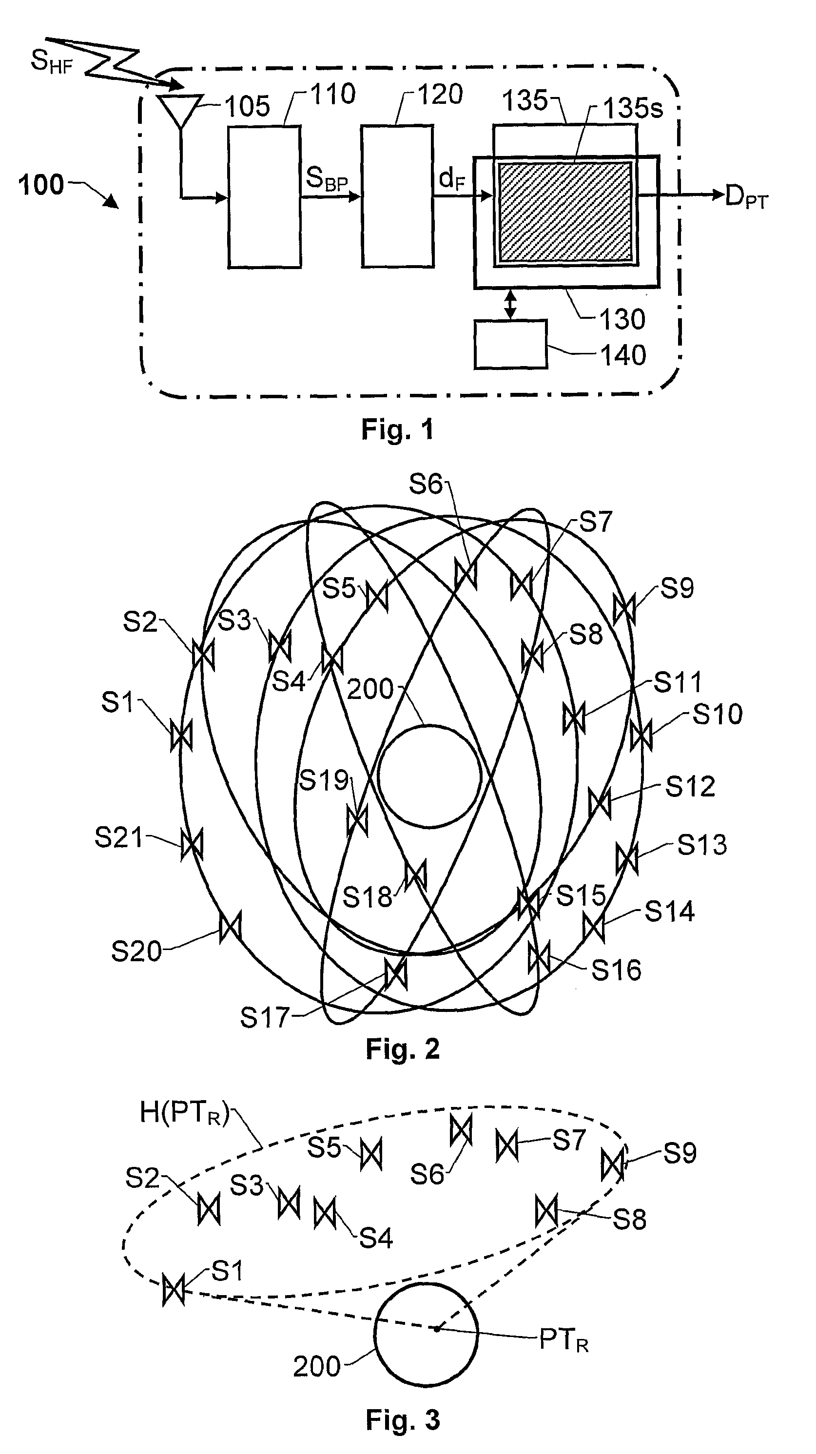
[0032]FIG. 1 shows a block diagram of a spread spectrum receiver 100 according to one embodiment of the invention. The receiver 100 includes a radio front-end unit 110, an interface unit 120 and a radio signal processing unit 135. The receiver 100 preferably also includes a computer readable medium 140, such as a memory buffer, storing a program which is adapted to control the processing unit 135 to operate according to the proposed principle.

[0033]The radio front-end unit 110 has an antenna means 105 adapted to receive radio signals SHF from a plurality of signal sources, for example a set of satellites belonging to one or more GNSSs. To this aim the antenna means is designed to receive radio frequency signals in at least one frequency band, e.g. the L1-, L2- and / or L5-bands, i.e. having spectra ranging from 1563 MHz to 1587 MHz, 1215 MHz to 1240 MHz and 1155 MHz to 1197 MHz respectively. Furthermore, the radio front-end unit 110 is adapted to perform sampling and digitizing of the...


PUM


Abstract

A spread spectrum signal receiver comprises a radio signal processing unit, at least partly implemented in software running on a processor. The processing unit determines a candidate collection of subsets of signal sources from a group of potential sources, by the criterion that an anticipated processing intensity required to derive position / time related data from that subset is equal to or less than a maximum specified processing intensity. Each subset contains at least a minimum number of signal sources necessary to produce position / time related data. The processing unit also selects a set of preferred signal sources from a candidate subset, based on a highest estimated quality of the position / time related data attainable during a subsequent operating period for the receiver without exceeding the maximum specified processing intensity. During the subsequent operating period, the receiver receives spread spectrum signals from the selected set of signal sources and produces position / time related data therefrom.

Description

THE BACKGROUND OF THE INVENTION AND PRIOR ART[0001]The present invention relates generally to reception and processing of spread spectrum signals. More particularly the invention relates to a spread spectrum receiver according to the preamble of claim 1 and a method according to the preamble of claim 11. The invention also relates to a computer program product according to claim 21 and a computer readable medium according to claim 22.[0002]Spread spectrum transmission solutions are becoming increasingly important, for instance in global navigation satellite systems (GNSS). Presently, the Global Positioning System (GPS; U.S. Government) is the dominant system, however alternative systems are expected to gain increased importance in the future. So far, the Global Orbiting Navigation Satellite System (GLONASS; Russian Federation Ministry of Defense) and the Galileo system (the European programme for global navigation services) constitute the major alternative GNSSs. Various systems als...

Claims


Application Information

Patent Timeline
IPC IPC(8): G01S1/00G01S19/28H04B1/707H04J13/00
CPCG01S19/33G01S19/28
Inventor NORMARK, PER-LUDVIG BORJEMITELMAN, ALEXANDER MICHAEL
Owner QUALCOMM TECH INT
Learn More