Eureka AIR delivers breakthrough ideas for toughest innovation challenges, trusted by R&D personnel around the world.

Power steering device

a technology of steering device and steering wheel, which is applied in the direction of power steering, fluid steering, vehicle components, etc., can solve the problems of deteriorating the steering feeling of the driver operating the steering wheel, excessively high counter,

Inactive Publication Date: 2009-01-01
HITACHI LTD
View PDF13 Cites 0 Cited by
  • Summary
  • Abstract
  • Description
  • Claims
  • Application Information

AI Technical Summary

Benefits of technology

[0008]The above-mentioned power steering device of Japanese Laid-open Patent Application exhibits a satisfied performance in producing a certain resistance that is felt by the driver when he or she turns the steering wheel for steering the motor vehicle. Such resistance is important for safely driving the motor vehicle.
[0012]Accordingly, it is an object of the present invention to provide a power steering device which is free of the above-mentioned drawback.
[0013]According to the present invention, there is provided a power steering device which not only exhibits a satisfied steering feeling under normal cruising of the vehicle, but also assists an automatic returning of the vehicle to the original lane in the above-mentioned emergency case.

Problems solved by technology

However, due to its inherent construction, this method inevitably brings about an excessively high counter torque at the time of steering the motor vehicle under normal cruising of the vehicle, which of course deteriorates a steering feeling with which the driver operates the steering wheel.

Method used


Image

  • Power steering device
  • Power steering device
  • Power steering device

Examples


first embodiment

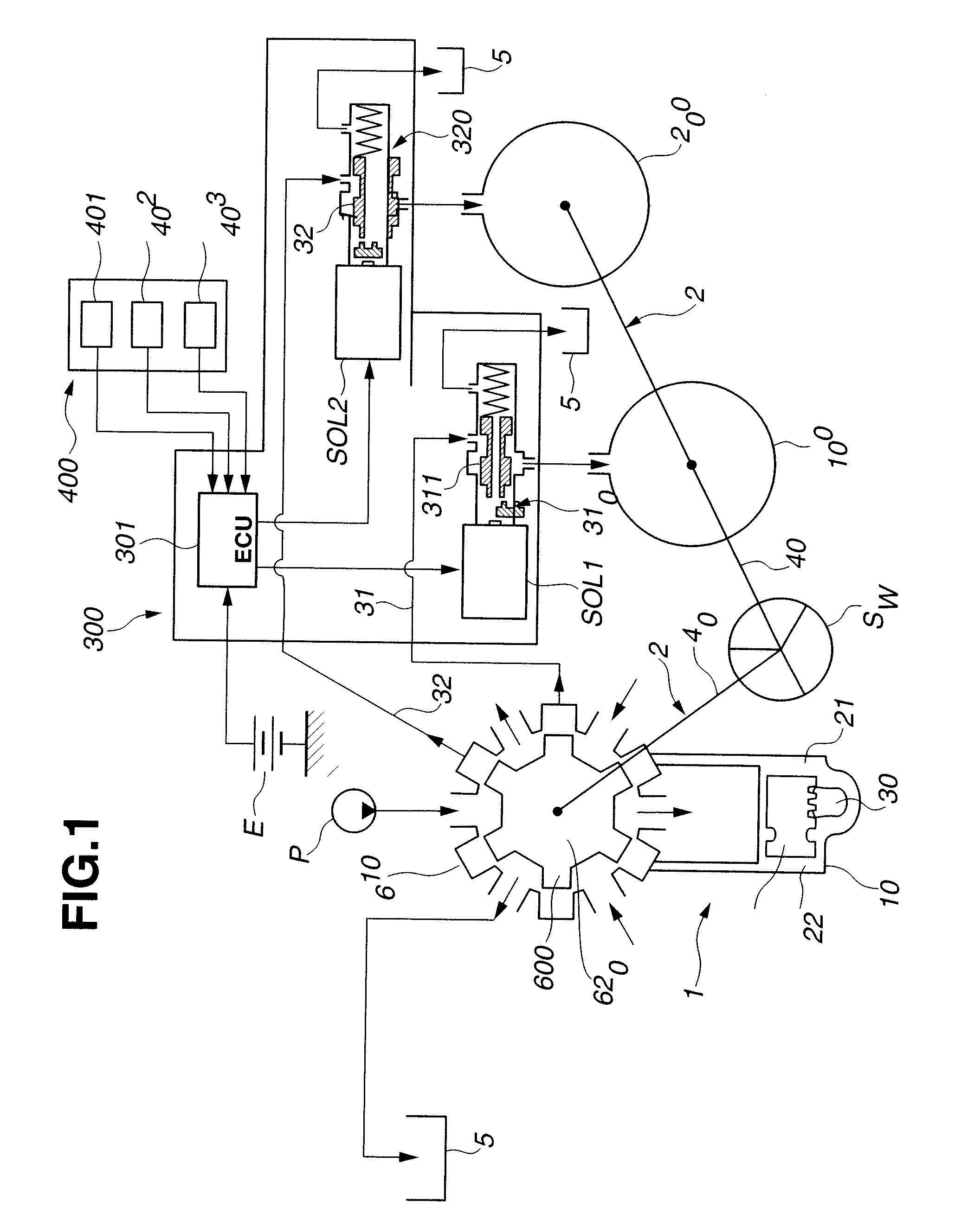
[0036]Referring to FIG. 1, there is shown a block diagram of a power steering device 1 of the present invention.

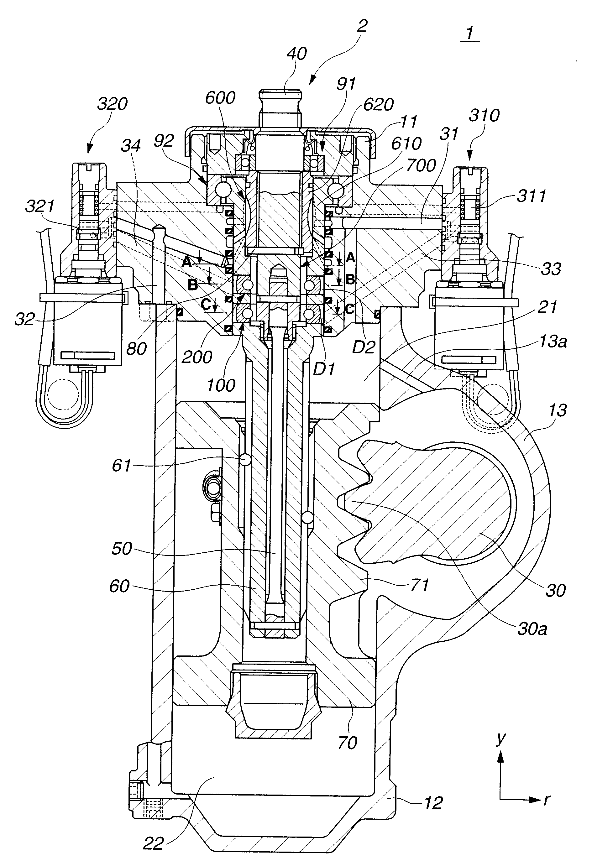
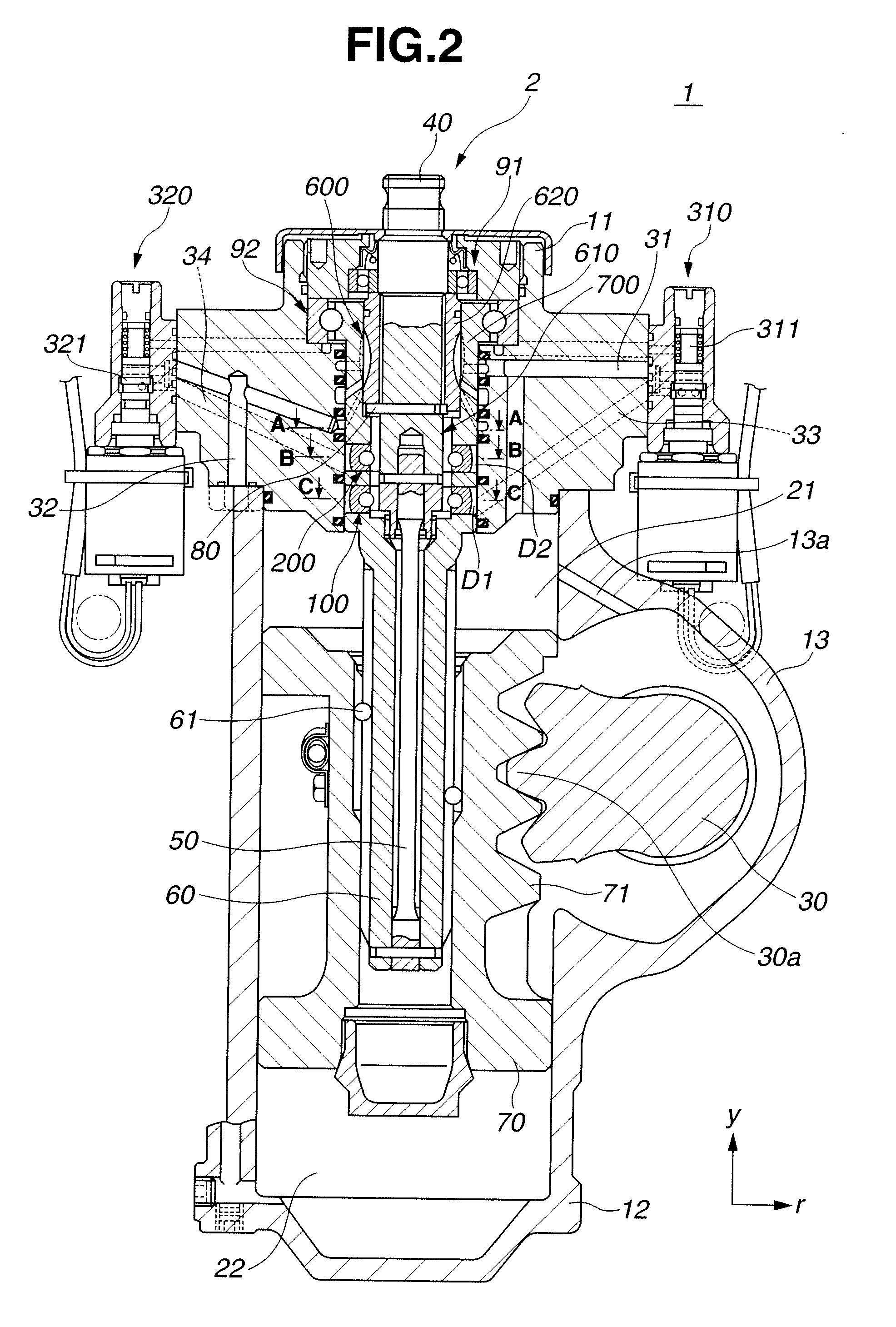
[0037]As shown in the drawing, power steering device 1 comprises a steering shaft 2 that is connected to a steering wheel SW to turn therewith, a rotary switch valve 600 that functions to switch or change the direction of power-assist, an assist-aimed piston 70 that is installed in a hydraulic power cylinder 10 to produce an assist force with the aid of a hydraulic pressure, and a sector shaft 30 that is meshed with assist-aimed piston 70 so that forward-and-backward movement of assist-aimed piston 70 includes rightward (or clockwise) and leftward (or counterclockwise) turning of sector shaft 30. Although not shown in the drawing, sector shaft 30 is linked to steered road wheels of an associated motor vehicle, so that the turning of sector shaft 30 induces powered right or left turning of the steered road wheels.

[0038]As is best seen from FIG. 2, steering shaft 2 comprises...

second embodiment

[0115]FIG. 15 is a view similar to FIG. 6, but showing the present invention.

[0116]In this second embodiment, a left-turn aimed contact surface 46 and a right-turn aimed contact surface 47 are formed on input shaft 40 in a manner to face right-turn aimed piston unit 220 (or left-turn aimed piston unit 120). As shown, left-turn aimed contact surface 46 comprises a first inclined surface 46a that is flat and a second inclined surface 46b that is smoothly curved, and right-turn aimed contact surface 47 comprises a first inclined surface 47a that is flat and a second inclined surface 47b that is smoothly curved.

[0117]Also in this second embodiment, in the first open range “S1” of rotary switch valve 600 (see FIG. 9), the imaginary arm length “L” is smaller than that of the comparative example, and at the third open range “S3” of rotary switch valve 600, the imaginary arm length “L” shows a satisfied value. Thus, the automatic returning of motor vehicle to the original lane is also estab...


PUM


Abstract

Right-turn and left-turn aimed input shaft drive mechanisms are provided, each comprising a piston unit that slides in a bore formed in an output shaft and a contact surface that is formed on an input shaft. Under normal cruising of a vehicle, a comfortable steering feeling is given by a relatively small counter torque that is produced by a contact between the piston unit and a second inclined surface of the contact surface, and upon stray running of the vehicle due to doze in driving or the like, a relatively large steering torque is produced by a contact between the piston unit and a first inclined surface of the contact surface. An inclination angle of the second inclined surface relative to a traveling path of the piston unit is greater than that of the first inclined surface.

Description

BACKGROUND OF THE INVENTION[0001]1. Field of the Invention[0002]The present invention relates in general to power steering devices that assist the driver to steer a motor vehicle with a hydraulic power, and more particularly to the power steering devices of an integral type that is commonly applied to a large-sized motor vehicle. More specifically, the present invention is concerned with power steering devices of a type that not only provides a driver with a satisfied steering feeling under normal cruising of the vehicle, but also assists an automatic returning of the vehicle to an original lane when the vehicle is subjected to a stray running due to doze in driving or the like.[0003]2. Description of the Related Art[0004]In order to clarify the present invention, the background of the above-mentioned type of the power steering devices will be briefly described in the following.[0005]The power steering device of such type generally comprises an input shaft that is rotated by a steer...

Claims


Application Information

Patent Timeline
IPC IPC(8): B62D5/06
CPCB62D5/0835
Inventor HASEBE, TORUSUNAGA, SOSUKEWATANABE, MASAKI
Owner HITACHI LTD
Why Eureka
Eureka Blog
Learn More