Self-propelled agricultural harvesting machine with loss-measuring device

a harvesting machine and self-propelled technology, applied in the field of agriculture, can solve the problems of insufficient detection, grain may fly over the sensor, and go undetected, and achieve the effect of preventing grain portions from falling off and simplifying the cleaning procedur

Inactive Publication Date: 2008-12-25
CLAAS SELBSTFAHRENDE ERNTEMASCHINEN GMBH
View PDF18 Cites 20 Cited by
  • Summary
  • Abstract
  • Description
  • Claims
  • Application Information

AI Technical Summary

Benefits of technology

[0010]The present invention is therefore based on the object of creating a loss-measuring device of the type described initially that prevents the aforementioned disadvantages of the known designs of the related art, and to provide a technical solution that makes it possible to support and / or simplify the cleaning procedure, in order to prevent a loss of grain portions due to poorly positioned sensors.

Problems solved by technology

This type of sensor has weak points in terms of detecting grain, however.
As a result, grain may fly over the sensor and go undetected.
The sensor also has disadvantages when it is used to thresh rapeseed, because the grain is so lightweight that it is inadequately detected.
The disadvantage of this placement of the sensors is that the grains that fall onto the sensor through the grid-like protective device fall to the ground after they are detected as cleaning loss, and they are not spread, thereby resulting in piles being formed.
Due to these piles and the subsequent germination of the grains and growth of plants, undesired strips of green form on the field.
That is, due to the sifting of chaff and influences by the radial straw spreader or the feed pan, the measurements performed by the loss-measuring device may be negatively affected, and a higher loss due to cleaning may be ascertained and displayed than actually exists, which could result in a maladjustment of the cleaning sieves and / or the upper sieve width, which, in turn, results in more non-grain portions in the grain tank contaminating the crop material.

Method used


Image

  • Self-propelled agricultural harvesting machine with loss-measuring device
  • Self-propelled agricultural harvesting machine with loss-measuring device
  • Self-propelled agricultural harvesting machine with loss-measuring device

Examples


Embodiment Construction

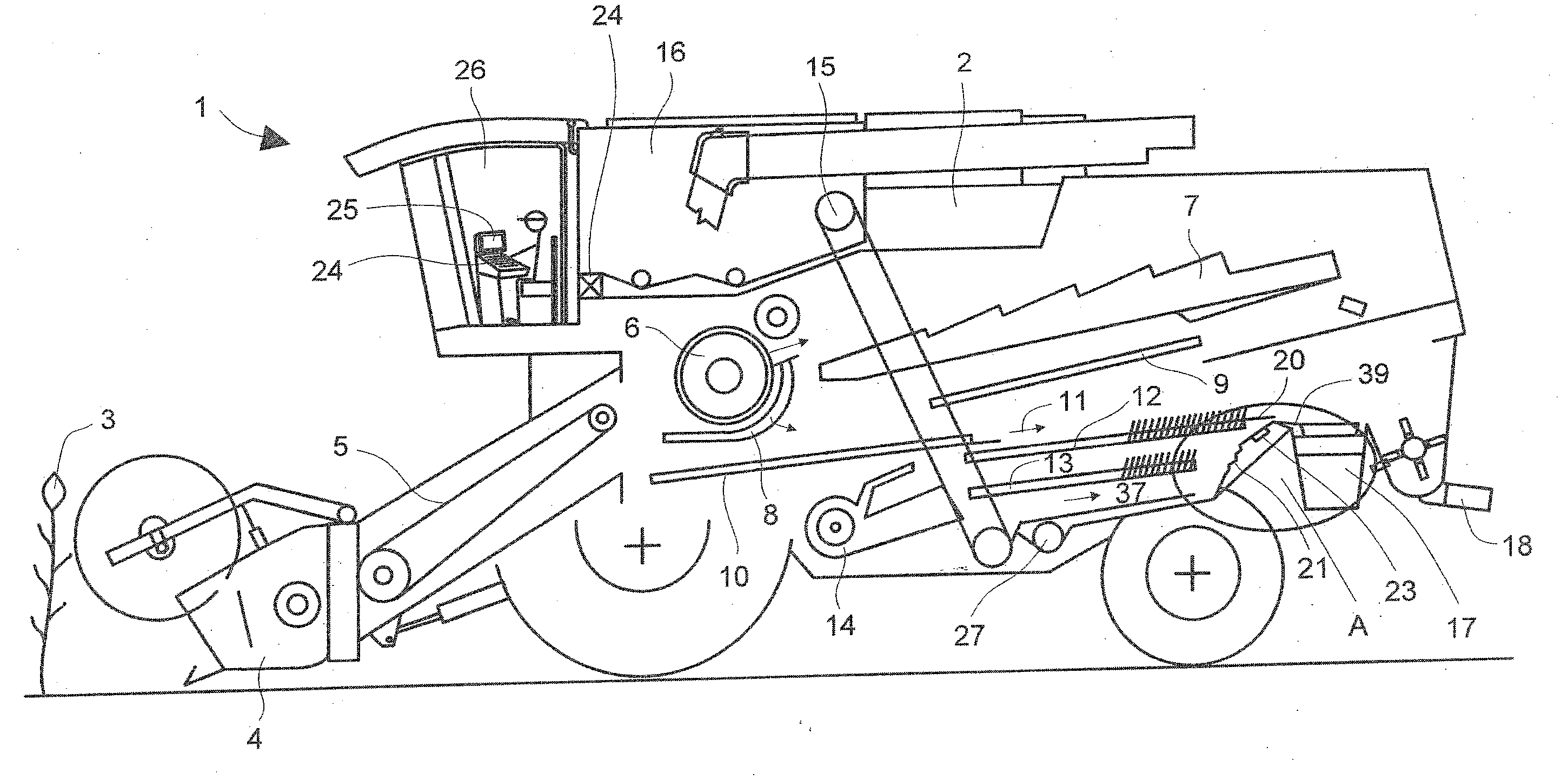
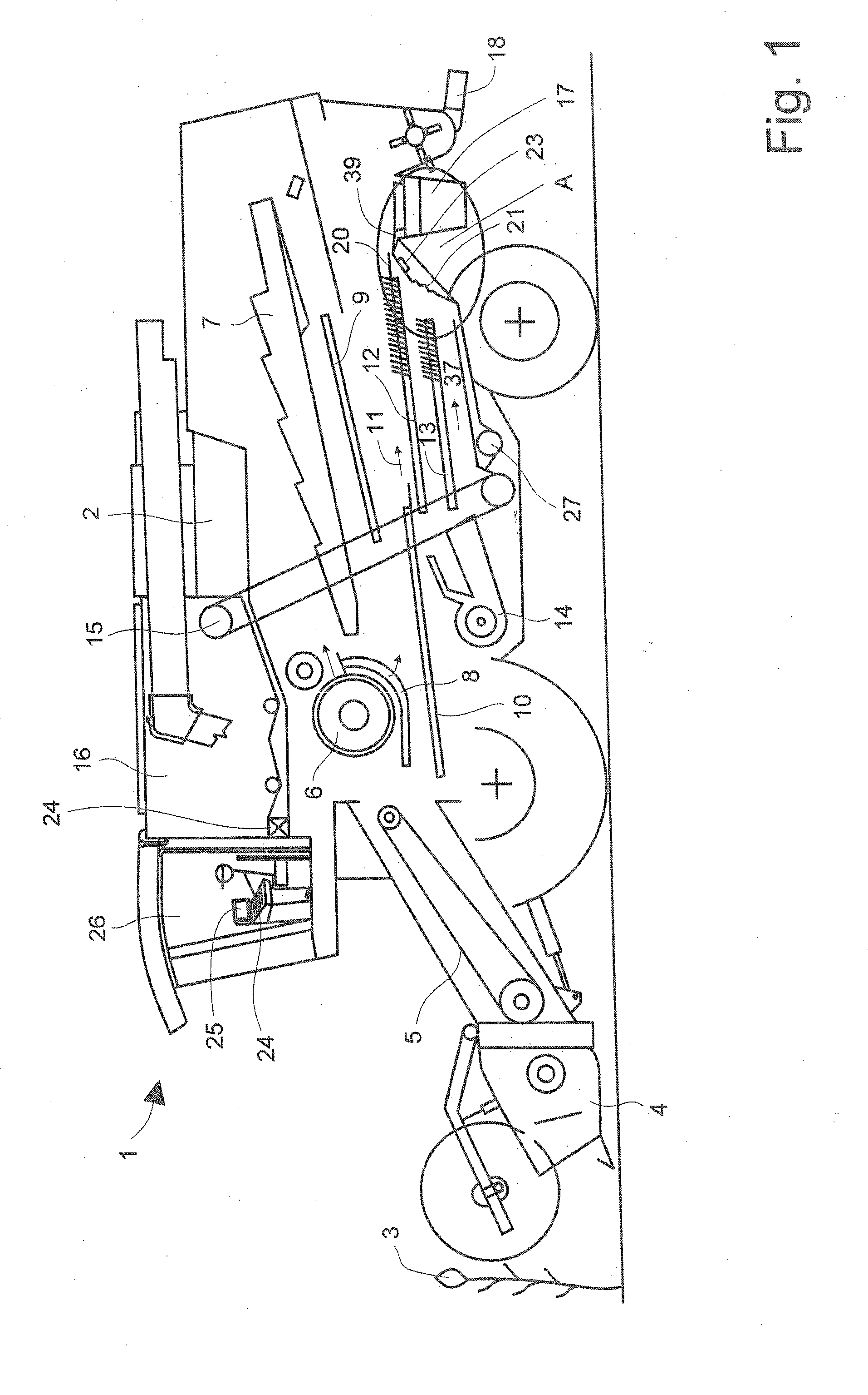
[0028]FIG. 1 is a schematic depiction of a self-propelled agricultural harvesting machine 1, which serves to pick up and process crop material 3. Self-propelled agricultural harvesting machine 1 is a combine harvester 2 equipped with a header 4, which—together with conveyor 5—conveys crop material 3 to cylinder 6, which is abutted by a tray-type shaker 7. A return pan 9 and a return device 10, which direct separated-out crop material 3 to a cleaning device 11 composed of an upper sieve 12 and a lower sieve 13, are located below concave 8 and tray-type shaker 7. Sieves 12, 13 are supplied with cleaning air, which is directed through and over sieves 12, 13 by a cleaning fan 14. Cleaned crop material 3 is conveyed by an elevator conveyor 15 into a grain tank 16, where it is collected. A crop material portion that is conveyed by tray-type shaker 7, e.g., straw, is directed via the rear part of combine harvester 2 to a radial spreader 18, which distributes the crop material portions onto...


PUM


Abstract

A self-propelled harvesting machine has a cleaning device having sieves, a loss-measuring device for the sieves of the cleaning device, at least one sensor having a sensor surface and located at a back end of the cleaning device, and the sensor is located at an end of the cleaning device behind at least one of the sieves such that a crop material that fails on the sensor surface and is detected remains in the harvesting machine and is conveyed to a tailings device.

Description

CROSS-REFERENCE TO A RELATED APPLICATION[0001]The invention described and claimed hereinbelow is also described in German Patent Application DE 10 2007 029 218.1 filed on Jun. 22, 2007. This German Patent Application, whose subject matter is incorporated here by reference, provides the basis for a claim of priority of invention under 35 U.S.C. 119(a)-(d).BACKGROUND OF THE INVENTION[0002]The present invention is based, in general, on the field of agriculture and the processing of harvested crops.[0003]Vehicles designed to pick up and process crops—in particular self-propelled agricultural harvesting machines—are used for this purpose. The self-propelled agricultural harvesting machines are typically combine harvesters that are equipped with devices for processing and conveying the crop material. The cleaning device, for instance, is a conveyance device of this type. The cleaning device is used to separate the crop material into the grain and non-grain portions. A cleaning device of t...

Claims


Application Information

Patent Timeline
Patent Type & Authority Applications(United States)
IPC IPC(8): A01D41/127
CPCA01D41/1273
Inventor BAUMGARTEN, JOACHIMBRUNE, MARKUSZURHAKE, CHRISTIAN
Owner CLAAS SELBSTFAHRENDE ERNTEMASCHINEN GMBH
Why Eureka
Try Eureka