
Sandwich panel

a technology of sandwich panels and sandwich sheets, which is applied in the field of sandwich sheets, can solve the problems that the character of the material cannot be met by simply changing the amount of fibers, and achieve the effects of reducing the misalignment of the interlayer layer of the laminating material, and reducing the amount of fibers

Active Publication Date: 2008-12-25
JAMCO +1
View PDF6 Cites 8 Cited by
  • Summary
  • Abstract
  • Description
  • Claims
  • Application Information

AI Technical Summary

Benefits of technology

[0007]In view of the foregoing drawbacks, the present invention provides a sandwich panel wherein each of the fibers in a plurality of unidirectional fiber bodies that constitute a middle layer (a laminating material) are oriented approximately at 0°, +45°, −45°, and 90°; and the unidirectional fiber bodies are stitched together with a stitching yarn (penetrating each layer), whereby the abovementioned requirements of flexural strength and in-plane shear strength can be satisfied while reducing weight and preventing misalignment between each layer in the laminating material. The sandwich panel of the present invention thus has exceptional utility as an inner wall material used in aircraft, for example.
[0014]The present invention is constituted as described above, and therefore provides a sandwich panel able to exhibit adequate flexural strength and in-plane shear strength while being light in weight and having minimal interlayer misalignment in the laminating material. The sandwich panel of the present invention thus has excellent practical value as an inner wall material used in aircraft, for example.

Problems solved by technology

These characteristics, however, cannot be met merely by changing the amount of fibers or by changing the number of fiber layers that constitute the middle layer.

Method used


Image

  • Sandwich panel
  • Sandwich panel
  • Sandwich panel

Examples


working example

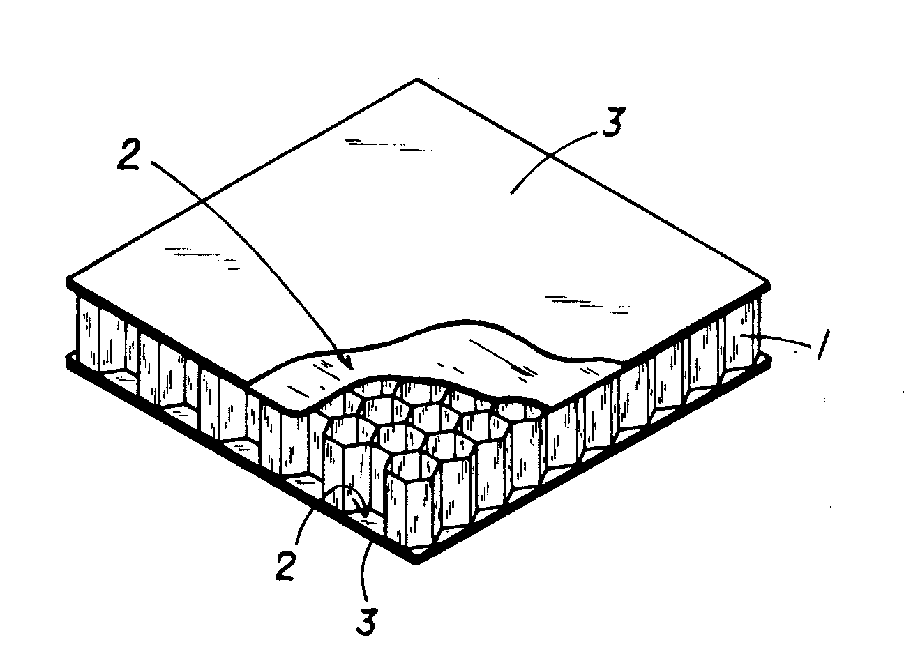
[0030]A specific working example of the present invention will be described based on the drawings.

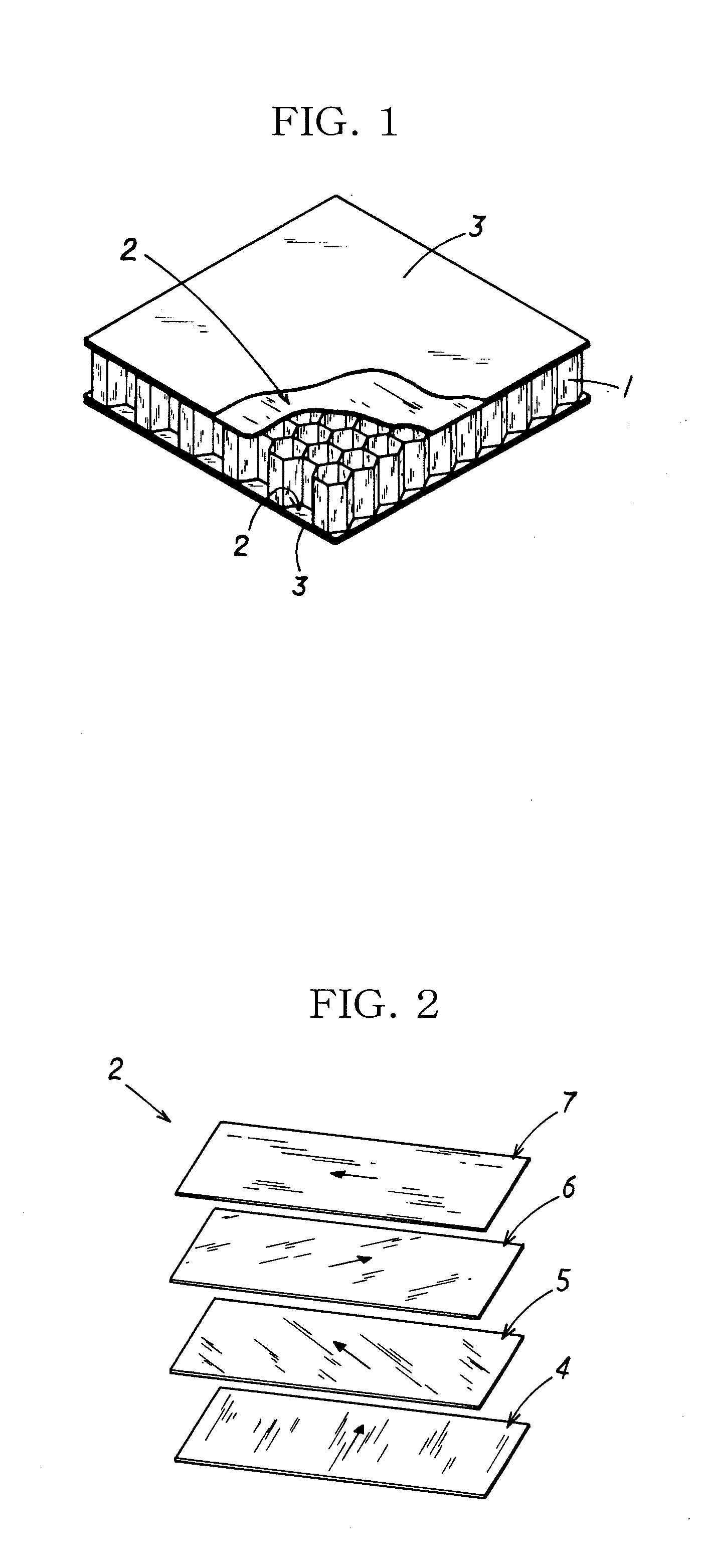
[0031]As shown in FIG. 1, the present working example is a sandwich panel in which a laminating material 2 formed by laminating a plurality of fiber bodies, and a surface material 3 are laminated in the stated order from the inside to the outside on upper and lower surfaces of a hollow columnar core 1. The laminating material 2 comprises unidirectional fiber bodies 4, 5, 6, 7, each of whose fiber direction is uniform in directions of approximately 0°, +45°, −45°, and 90° in relation to one edge of the sandwich panel. The unidirectional fiber bodies 4, 5, 6, 7 are stitched together using a stitching yarn 8.

[0032]In particular, as shown in FIG. 2, the unidirectional fiber bodies 4, 5, 6, 7 are laminated in the stated order from the inside to the outside to constitute the laminating material 2.

[0033]A fiber direction of the unidirectional fiber body 4 is set to approximately 0° (substantia...


PUM

PropertyMeasurementUnit
Fractionaaaaaaaaaa
Angleaaaaaaaaaa
Angleaaaaaaaaaa

Abstract

There is provided a lightweight sandwich panel of exceptional utility, which satisfies the flexural strength and in-plane shear strength requirements for an inner wall material used in aircraft. The sandwich panel comprises a laminating material in which a plurality of fiber bodies_is laminated, and a surface material, the laminating material and the surface material being laminated in the stated order from the inside to the outside on the upper and lower surfaces of a hollow columnar core. The laminating material comprises at least four unidirectional fiber bodies each of which has fibers aligned in a uniform direction and is laminated so that each of the fiber directions thereof is at approximately 0 , +45°, −45°, and 90°, respectively, in relation to one edge of the sandwich panel. The unidirectional fiber bodies are stitched together using a stitching yarn.

Description

BACKGROUND OF THE INVENTION[0001]1. Field of the Invention[0002]The present invention relates to a sandwich panel.[0003]2. Description of the Related Art[0004]Honeycomb sandwich panels disclosed in Examined Utility Model Application Publication No. 6-17530 or the like have been used in the past. In such honeycomb sandwich panels, carbon (C) fiber-reinforced plastic bodies are laminated as middle layers onto both upper and lower surfaces (both open end surfaces) of a honeycomb core in which hollow columnar cells are aggregated in a plane, and surface members are laminated on the carbon (C) fiber-reinforced plastic bodies.[0005]Since lightness of weight is associated with better performance in terms of the fuel consumption of aircraft or the like, the weight of the structural and interior materials needs to be reduced. The honeycomb sandwich panel described above, in which fiber-reinforced plastic panels are placed above and below a honeycomb core, is used as a material that yields su...

Claims


Application Information

Patent Timeline
IPC IPC(8): B32B3/12
CPCB32B3/12B32B5/02E04C2/365B32B2260/046B32B2262/101B32B2262/106B32B2307/50B32B2307/542B32B2307/546B32B2307/718B32B2605/003B32B2605/18Y10T428/249953Y10T428/24149Y10T428/254Y10T428/24744Y10T428/1314
Inventor HORIGOME, HIROSHITANAKA, YASUNOBUHIRAI, MASAAKITANAKA, HIROSHI
Owner JAMCO
Learn More