
Composite charged-particle beam system

a charged particle and beam system technology, applied in the field of composite charged particle beam system, can solve the problems of damage, further restriction of the space in which charged particle beam apparatuses can be arranged freely, and difficult to arrange all the beam apparatuses under preferable conditions, so as to achieve less damage, suppress damage, and efficiently prepare a tem sample

Active Publication Date: 2008-12-25
HITACHI HIGH TECH SCI CORP
View PDF15 Cites 23 Cited by
  • Summary
  • Abstract
  • Description
  • Claims
  • Application Information

AI Technical Summary

Benefits of technology

[0012]In view of the circumstances described above, an object of the present invention is to provide a method of configuring a composite charged-particle beam system capable of efficiently preparing a TEM sample without impairing an advantage of suppressing damage due to irradiation of an inert gas ion such as argon at a low acceleration, a technique of preparing a sample with high accuracy with the use of a high-performance FIB, and a function of observing an endpoint of a laminating process with the use of a high-performance SEM for forming a laminated specific portion of a semiconductor fine pattern.
[0015]According to the present invention, the FIB apparatus performs the laminating process for preparing a laminated sample such that a surface of the sample faces the SEM, so that a user can observe the surface with the use of the SEM during the process without moving the stage. After completion of the laminating process in this state, the axis of the gas ion beam is parallel with the surface of the laminated sample. In order to prepare the sample with less damage, desirably, the gas ion beam is irradiated on the sample surface at a small angle. Herein, the gas ion beam is irradiated at the time when the laminating process using the FIB is completed. Therefore, the sample can be subjected to a finishing process using the gas ion beam by being tilted only at an appropriate angle. Herein, when the gas ion beam is irradiated on the surface of the laminated sample at a narrow angle, the surface of the laminated sample can hold a relatively wide angle relative to the SEM. Therefore, the user can observe the sample without changing the state. Also in a case where the user must observe the sample which correctly faces the SEM, the sample can be moved to an observation position with little stage movement. According to the present invention, as described above, it is possible to configure a composite charged-particle beam system capable of efficiently preparing a TEM sample without impairing an advantage of suppressing damage due to irradiation of a gas ion at a low acceleration, a technique of preparing a sample with high accuracy with the use of a high-performance FIB, and a function of observing an endpoint of a laminating process with the use of a high-performance SEM for forming a laminated specific portion of a semiconductor fine pattern.

Problems solved by technology

However, the FIB causes a problem of damage due to a focused ion beam as a required thickness of a sample becomes small.
However, as beam apparatuses to be integrated with one another increase in number, it is difficult to arrange all the beam apparatuses under preferable conditions.
Secondly, a sample such as a semiconductor wafer is subjected to observation and fabrication while being tilted; therefore, a space for tilting the sample must be ensured in a sample chamber, resulting in further restriction of a space in which charged-particle beam apparatuses can be arranged freely.
Thirdly, with regard to a sample stage, it is difficult to sufficiently improve a degree of freedom of the stage for all charged-particle beams from the viewpoint of space, accuracy, rigidity and cost.

Method used


Image

  • Composite charged-particle beam system
  • Composite charged-particle beam system
  • Composite charged-particle beam system

Examples


first embodiment

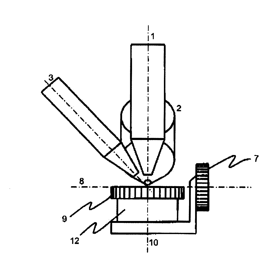
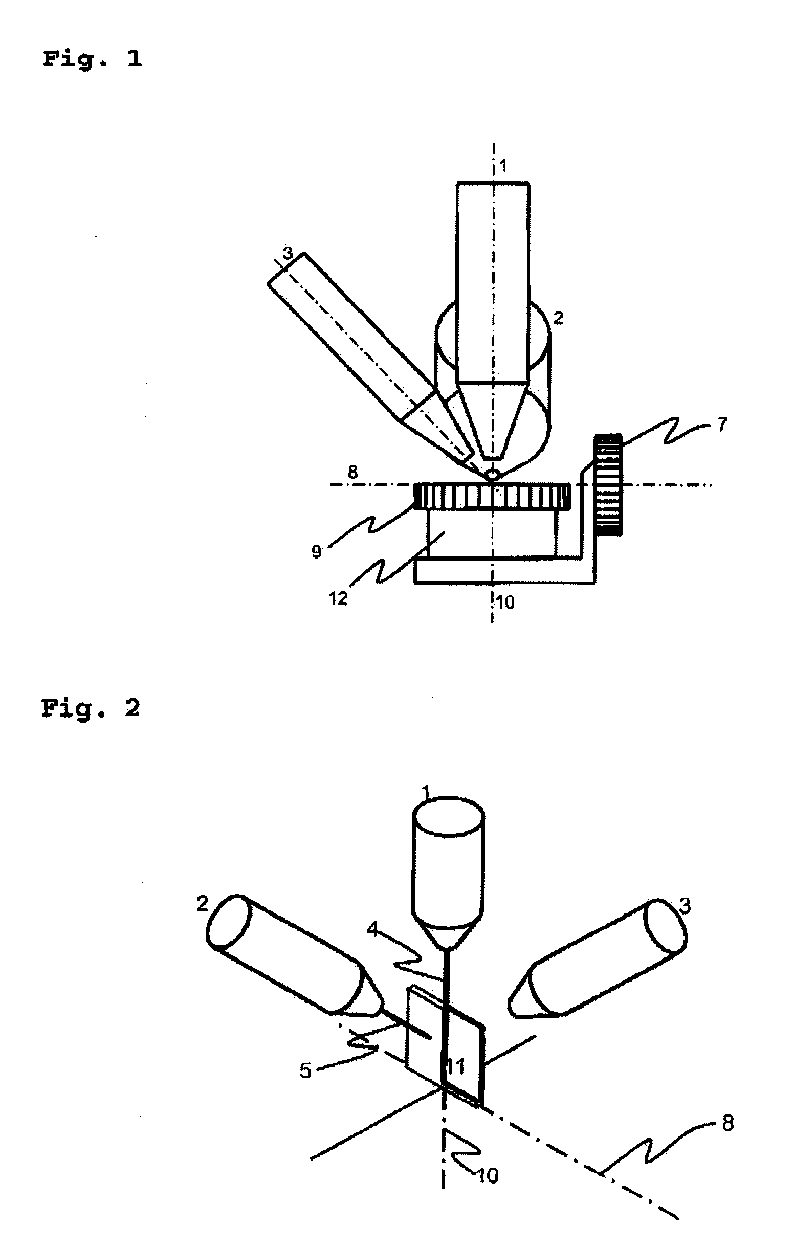
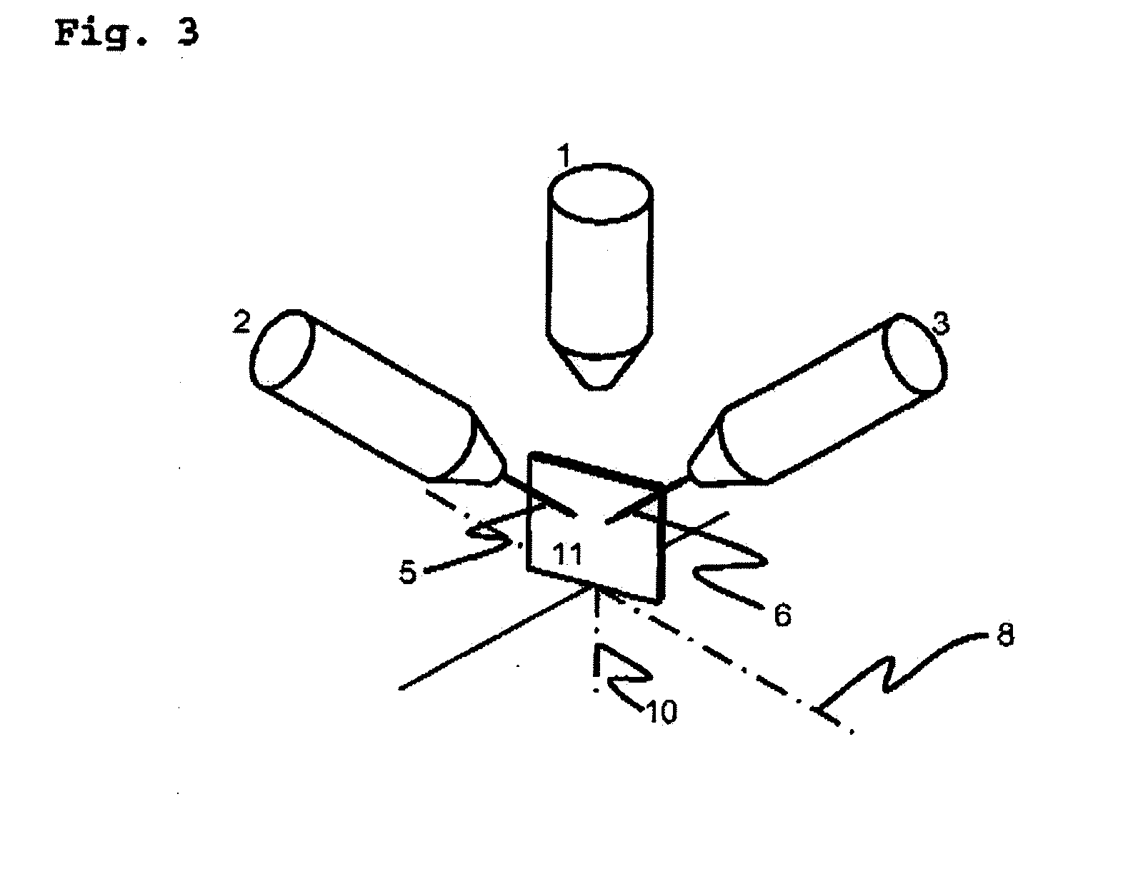
[0020]FIG. 1 schematically shows a composite charged-particle beam system according to a first embodiment of the present invention. In the present invention, a type of an ion to be used as a gas ion beam 6 is not an essential matter. In this embodiment, however, an argon ion beam is used as the gas ion beam 6.

[0021]As shown in FIG. 1, an FIB lens-barrel 1, an SEM lens-barrel 2 and a gas ion beam lens-barrel 3 are designed such that axes thereof intersect at a single point, and respectively have a mechanism for making adjustment such that actual beams therefrom also intersect at one intersection point. In the following, a coordinate system with the beam intersection point as an origin is used for representing a relation among the FIB lens-barrel 1, the SEM lens-barrel 2, the gas ion beam lens-barrel 3, an eucentric tilt axis 8 and a rotating shaft 10. Orientation of each axis is represented by an angle from a horizontal plane (hereinafter, referred to as an elevation angle) and an an...


PUM

PropertyMeasurementUnit
azimuth anglesaaaaaaaaaa
elevation angleaaaaaaaaaa

Abstract

There is provided a method of arranging, as a composite charged-particle beam system, a gas ion beam apparatus, an FIB and an SEM in order to efficiently prepare a TEM sample. The composite charged-particle beam system includes an FIB lens-barrel 1, an SEM lens-barrel 2, a gas ion beam lens-barrel 3, and a rotary sample stage 9 having an eucentric tilt mechanism and a rotating shaft 10 orthogonal to an eucentric tilt axis 8. In the composite charged-particle beam system, an arrangement is made such that a focused ion beam 4, an electron beam 5 and a gas ion beam 6 intersect at a single point, an axis of the FIB lens-barrel 1 and an axis of the SEM lens barrel 2 are orthogonal to the eucentric tilt axis 8, respectively, and the axis of the FIB lens-barrel 1, an axis of the gas ion beam lens-barrel 3 and the eucentric tilt axis 8 are in one plane.

Description

[0001]This application is a continuation of PCT / JP2006 / 323750 filed Nov. 29, 2006, which claims priority to JP2005-355734 filed Dec. 9, 2005, the entire content of which is incorporated herein by reference.TECHNICAL FIELD[0002]The present invention relates to a composite charged-particle beam system having a plurality of charged-particle beam apparatuses coupled to one another.BACKGROUND ART[0003]As a pattern of a semiconductor device becomes finer, recently, a technique of observing and evaluating a speck minute portion of the semiconductor device with the use of a TEM (Transmission Electron Microscope) has increasingly become important. In order to prepare a laminated sample serving as such a specific minute portion, an FIB (Focused Ion Beam) apparatus is used typically. However, the FIB causes a problem of damage due to a focused ion beam as a required thickness of a sample becomes small. Therefore, a method for removing such damage has been required.[0004]As a solution of the si...

Claims


Application Information

Patent Timeline
Patent Type & Authority Applications(United States)
IPC IPC(8): G01N23/00
CPCH01J37/20H01J37/3056H01J2237/20242H01J2237/31745H01J2237/31749
Inventor TAKAHASHI, HARUOYAMAMOTO, YOFUJII, TOSHIAKI
Owner HITACHI HIGH TECH SCI CORP
Learn More