
Abnormality diagnosis device and control system for internal combustion engine

a multi-cylinder, internal combustion engine technology, applied in the direction of electrical control, process and machine control, instruments, etc., can solve the problem that abnormal diagnosis cannot be performed appropriately

Inactive Publication Date: 2008-12-18
DENSO CORP
View PDF2 Cites 15 Cited by
  • Summary
  • Abstract
  • Description
  • Claims
  • Application Information

AI Technical Summary

Benefits of technology

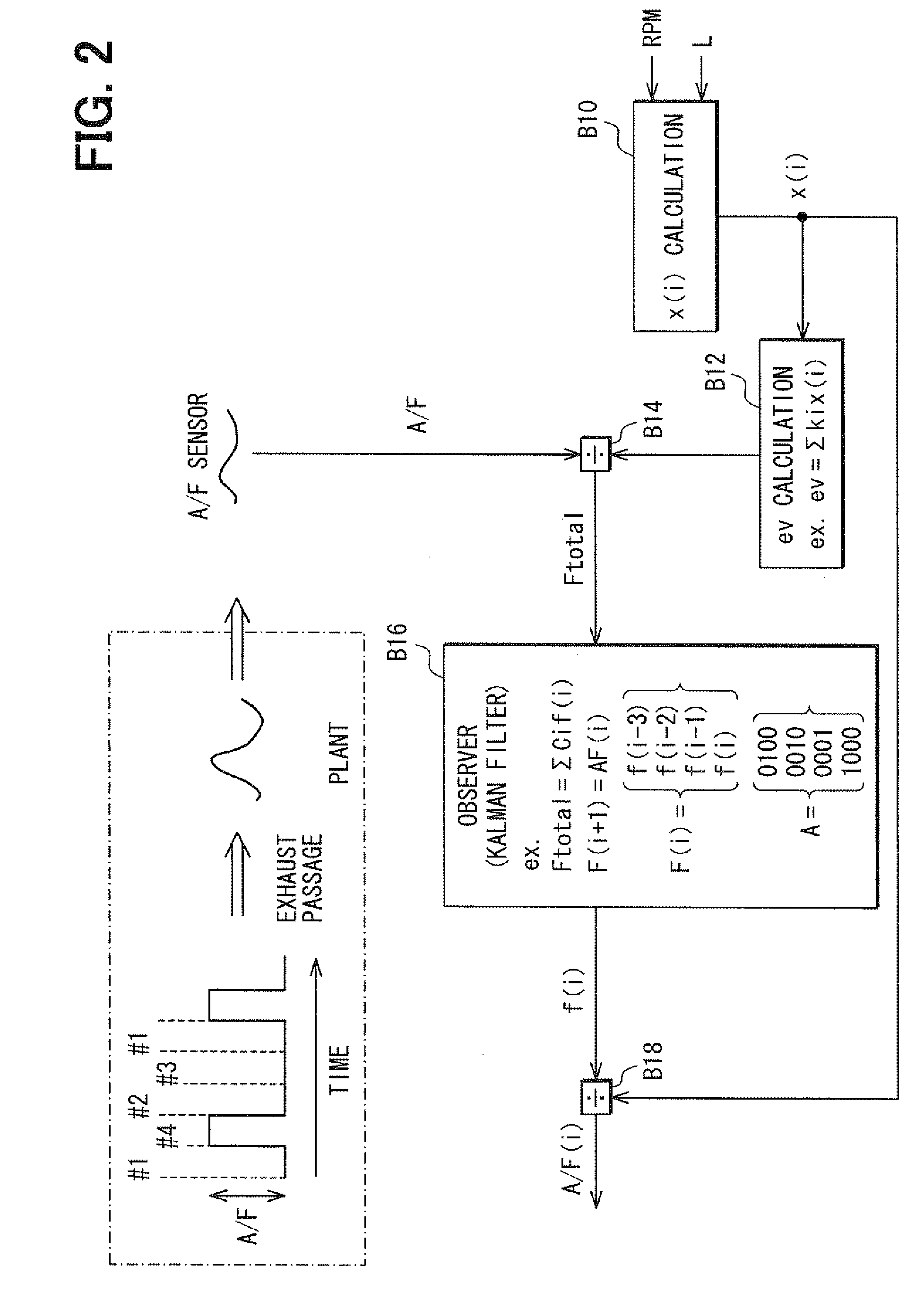
The present invention provides an abnormality diagnosis device for a multi-cylinder internal combustion engine that can appropriately diagnose the presence or absence of an abnormality in the air-fuel ratio of each cylinder based upon a sensing value of an air-fuel ratio sensing device disposed downstream of the junction where exhaust gases discharged from multiple cylinders converge. The device includes an air-fuel ratio sensing device, a diagnosing device, an increasing device, and a restricting device. The increasing device increases the intake air quantity to remove the prohibition caused by the small quantity of exhaust gas when the individual air-fuel ratio of each cylinder is small. The restricting device restricts the increase in torque due to the increase in intake air quantity. The diagnosing device determines the presence or absence of an abnormality when the air-fuel ratio sensing device senses a variation in the air-fuel ratio among the cylinders equal to or greater than a predetermined value. The device can easily and accurately diagnose abnormalities in the air-fuel ratio of each cylinder.

Problems solved by technology

When the quantity of the exhaust gas discharged from each cylinder per exhaust stroke is small, the abnormality diagnosis cannot be performed appropriately.

Method used


Image

  • Abnormality diagnosis device and control system for internal combustion engine
  • Abnormality diagnosis device and control system for internal combustion engine
  • Abnormality diagnosis device and control system for internal combustion engine

Examples


Embodiment Construction

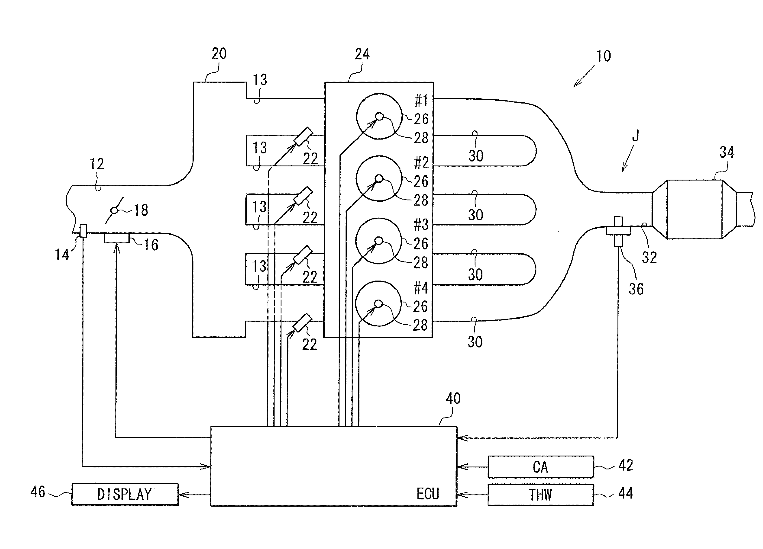
[0028]Hereinafter, an abnormality diagnosis device and a control system for an internal combustion engine according to a first embodiment of the present invention will be explained with reference to the drawings. FIG. 1 shows an entire construction of a control system according to the present embodiment. An air flow meter 14 for sensing an intake air quantity is provided in an upstream portion of an intake passage 12 of an internal combustion engine 10 as an intake port injection type gasoline engine. An electronically-controlled type intake throttle valve 18 is provided downstream of the air flow meter 14. The intake throttle valve 18 is driven by a motor 16 and adjusts a flow passage area of the intake passage 12. A surge tank 20 is provided by enlarging the flow passage area (or a diameter) of the intake passage 12 downstream of the throttle valve 18 for preventing intake pulsation, intake interference and the like.

[0029]A part of the intake passage 12 downstream of the surge tan...


PUM


Abstract

An exhaust gas discharged from a combustion chamber of each cylinder flows near an air-fuel ratio sensor via a junction. An ECU estimates an air-fuel ratio of each cylinder based upon a sensing value of an air-fuel ratio sensor. When a variation in the air-fuel ratio among the cylinders is equal to or greater than a predetermined value, the ECU determines that an abnormality exists in the air-fuel ratio. When a quantity of the exhaust gas discharged from each cylinder is less than another predetermined value, an intake air quantity is increased and ignition timing is delayed before the determination of presence or absence of the abnormality.

Description

CROSS REFERENCE TO RELATED APPLICATION[0001]This application is based on and incorporates herein by reference Japanese Patent Application No. 2007-157568 filed on Jun. 14, 2007.BACKGROUND OF THE INVENTION[0002]1. Field of the Invention[0003]The present invention relates to an abnormality diagnosis device and a control system of a multi-cylinder internal combustion engine having a diagnosing device for diagnosing presence or absence of an abnormality in an individual air-fuel ratio of each of multiple cylinders based upon a sensing value of an air-fuel ratio sensing device arranged downstream of a junction of the engine where exhaust gases discharged respectively from the multiple cylinders converge.[0004]2. Description of Related Art[0005]As an abnormality diagnosis device of this type, there is a proposed abnormality diagnosis device that diagnoses presence or absence of an abnormality in an air-fuel ratio of an arbitrary cylinder by comparing the air-fuel ratio of the arbitrary cy...

Claims


Application Information

Patent Timeline
Patent Type & Authority Applications(United States)
IPC IPC(8): F02D41/00
CPCF02D41/008F02D41/1454F02D41/1458F02D41/1495F02D41/222F02P5/151Y02T10/46Y02T10/40
Inventor UEDA, KUNIAKI
Owner DENSO CORP
Learn More