Devices and methods for measuring the space around a nerve root

Inactive Publication Date: 2008-12-18
BAXANO
View PDF198 Cites 65 Cited by
  • Summary
  • Abstract
  • Description
  • Claims
  • Application Information

AI Technical Summary

Benefits of technology

[0020]Any of the methods described herein may include the step of applying neural stimulation from the measurement device and monitoring for EMG signals. Neural stimulation may be applied from one or more discrete regions, sections, sub-regions or subsections along the measurement device. In some variations the neural stimulation is applied by use of one or more “tight bipole pairs.” Thus, current may be applied to one or more bipole pairs on the surface of the device that are only slightly separated, or separated by a small distance (e.g., less than a few millimeters, less than 1 mm, etc). The exposed surfaces of the anode and cathode forming the bipole are typically also small (e.g., less than 2 mm2, less than 1 mm2, etc.). In some variations, neural stimulation is applied by the measurement device to determine which portion of the measurement device a nerve within the intervertebral foramen is near-contacting or contacting; the regions may be independently activated and correlated to a known diameter. In this way, the diameter of the intervertebral foramen nearest a nerve (e.g., the nerve root) may be determined. In some variations, neural stimulation may be used to help properly advance and position the measurement device.
[0028]Also described herein are methods for measuring the size of a compliant region adjacent to a patient's nerve root that include electrical stimulation that may help identify the proximity of the measurement device to the nerve root as the measurement device is advanced. This electrical stimulation may prevent damaging (e.g., crushing or applying undesirable pressure) to the nerve root. For example, the method may include the steps of: advancing a guidewire from a first position outside of the patient's body, through an intervertebral foramen, and out of the patient's body at a second position, applying an electrical current between a pair of tight bipolar electrodes on a measurement device, advancing the measurement device until the patient's nerve root is stimulated by the applied electrical current, wherein the measurement device is coupled to the guidewire, and estimating a size of the region adjacent to the nerve root, based on the advancement of the measurement device.
[0039]Also described herein are devices for percutaneously measuring an intervertebral foramen as part of a spinal decompression procedure, the devices having: a flexible catheter configured to pass through an intervertebral foramen, the catheter having proximal and distal portions, and an expansion region, a plurality of long, flexible expansion members configured to pass into the expansion region, wherein the expansion region is configured to expand as the expansion members are passed therein, and a guidewire coupling region configured to couple the catheter with a guidewire that can advance the catheter into the foramen.

Problems solved by technology

Developing less invasive surgical methods and devices, however, poses many challenges.
These challenges are often compounded when target tissues of a given procedure reside very close to one or more vital, non-target tissues.
The most common form of spinal stenosis occurs in the lower (or lumbar) spine and can cause severe pain, numbness and / or loss of function in the lower back and / or one or both lower limbs.
Impingement of neural and / or neurovascular tissue in the spine by one or more of these tissues may cause pain, numbness and / or loss of strength or mobility in one or both of a patient's lower limbs and / or of the patient's back.
When these conservative treatment options fail and symptoms are severe, as is frequently the case, surgery may be required to remove impinging tissue and decompress the impinged nerve tissue.
Removal of vertebral bone, as occurs in laminectomy and facetectomy, often leaves the effected area of the spine very unstable, leading to a need for an additional highly invasive fusion procedure that puts extra demands on the patient's vertebrae and limits the patient's ability to move.
Unfortunately, a surgical spine fusion results in a loss of ability to move the fused section of the back, diminishing the patient's range of motion and causing stress on the discs and facet joints of adjacent vertebral segments.
Such stress on adjacent vertebrae often leads to further dysfunction of the spine, back pain, lower leg weakness or pain, and / or other symptoms.
Furthermore, using current surgical techniques, gaining sufficient access to the spine to perform a laminectomy, facetectomy and spinal fusion requires dissecting through a wide incision on the back and typically causes extensive muscle damage, leading to significant post-operative pain and lengthy rehabilitation.
Thus, while laminectomy, facetectomy, and spinal fusion frequently improve symptoms of neural and neurovascular impingement in the short term, these procedures are highly invasive, diminish spinal function, drastically disrupt normal anatomy, and increase long-term morbidity above levels seen in untreated patients.
One challenge in treating spinal stenosis using minimally invasive tools is discerning how much space exists in the intervertebral foramen through which a given impinged nerve runs.
Making this determination in a minimally invasive setting may be quite challenging, since direct visualization of a foramen is typically not possible and soft tissues such as ligamentum flavum and nerve tissue are difficult or impossible to visualize with intraoperative fluoroscopy.
Although such probes may work in some cases in a traditional, open surgical procedure, such rigid probes will generally not be useful for a minimally invasive or percutaneous procedure.
Again, this device is not configured to work in a minimally invasive or percutaneous procedure.

Method used


Image

  • Devices and methods for measuring the space around a nerve root
  • Devices and methods for measuring the space around a nerve root
  • Devices and methods for measuring the space around a nerve root

Examples


Embodiment Construction

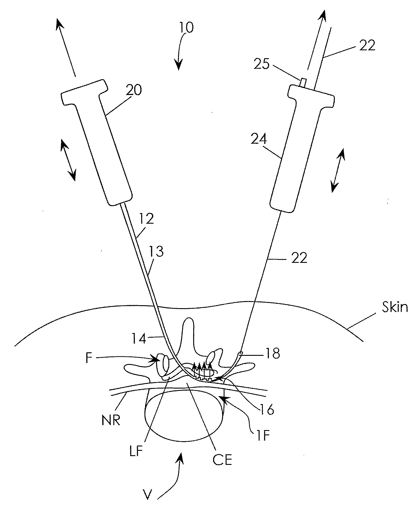
[0072]The present invention is directed primarily to medical / surgical devices, systems and methods for measuring the compliant region adjacent to a nerve root before, during and / or after a spine tissue removal procedure (or “decompression procedure”) of a constricted region surrounding the nerve root (e.g., within an intervertebral foramina, spinal canal and / or lateral recess). The devices, methods and systems described herein may be used with any appropriate spinal treatment, including those described in: U.S. patent application Ser. No.: 11 / 251,205, entitled “Devices and Methods for Tissue Access,” and filed Oct. 15, 2005; U.S. patent application Ser. No.: 11 / 457,416, entitled “Spinal Access and Neural Localization,” and filed Jul. 13, 2006; U.S. patent application Ser. No.: 11 / 468,247, entitled “Tissue Access Guidewire System and Method,” and filed Aug. 29, 2006; U.S. patent application Ser. No.: 11 / 251,165, entitled “Devices and Methods for Tissue Modification,” and filed Oct. 1...


PUM


Abstract

Described herein are method, systems and devices for measuring the region adjacent to or around a nerve root, such as the space within an intervertebral foramen before, during and / or after a spinal decompression procedure. Measurement devices may be advanced by pulling on them using a guidewire passing through the intervertebral foramen and out of the subject. The measurement device may include sounds for determining one or more dimensions of the space around a nerve root within an intervertebral space, lateral recess or central canal. Various embodiments of sounds, including calibrated, inflatable, expandable, moldable, and tapered sounds (or combinations of these) are described.

Description

CROSS-REFERENCE TO RELATED APPLICATIONS[0001]This application claims the benefit of U.S. Provisional Patent Application Ser. No. 60 / 944,398, titled “Neural Foramen Measurement Devices,” filed on Jun. 15, 2007.BACKGROUND OF THE INVENTION[0002]The present invention relates generally to medical / surgical devices and methods. More specifically, the present invention relates to devices and methods for measuring the size of a compliant region adjacent to a patient's nerve root, such as the intervertebral foramina, central canal, and / or lateral recess in a spine.[0003]In recent years, less invasive (or “minimally invasive”) surgical techniques have become increasingly more popular, as physicians, patients and medical device innovators have sought to reduce the trauma, recovery time and side effects typically associated with conventional surgery. Developing less invasive surgical methods and devices, however, poses many challenges. For example, less invasive techniques typically involve work...

Claims


Application Information

Patent Timeline
IPC IPC(8): A61B17/58A61B19/00A61B5/00
CPCA61B5/1076A61B5/4504A61B5/4533A61B17/320016A61B19/46A61B2017/00261A61B2017/320008A61B2019/461A61B2019/463A61B2090/063A61B90/06A61B2090/061
Inventor BLEICH, JEFFERY L.SCHMITZ, GREGORY P.MILLER, ERIC C.VILLALTA, MICHAELBLEAM, JEFFEREYYURCHENCO, JAMESWALLACE, MICHAEL P.
Owner BAXANO
Why Eureka
Try Eureka