Direct bond bracket application instrument
- Summary
- Abstract
- Description
- Claims
- Application Information
AI Technical Summary
Benefits of technology
Problems solved by technology
Method used
Image
Examples
Embodiment Construction
—FIGS. 1, 2, 3, 4, 5, 6, 7
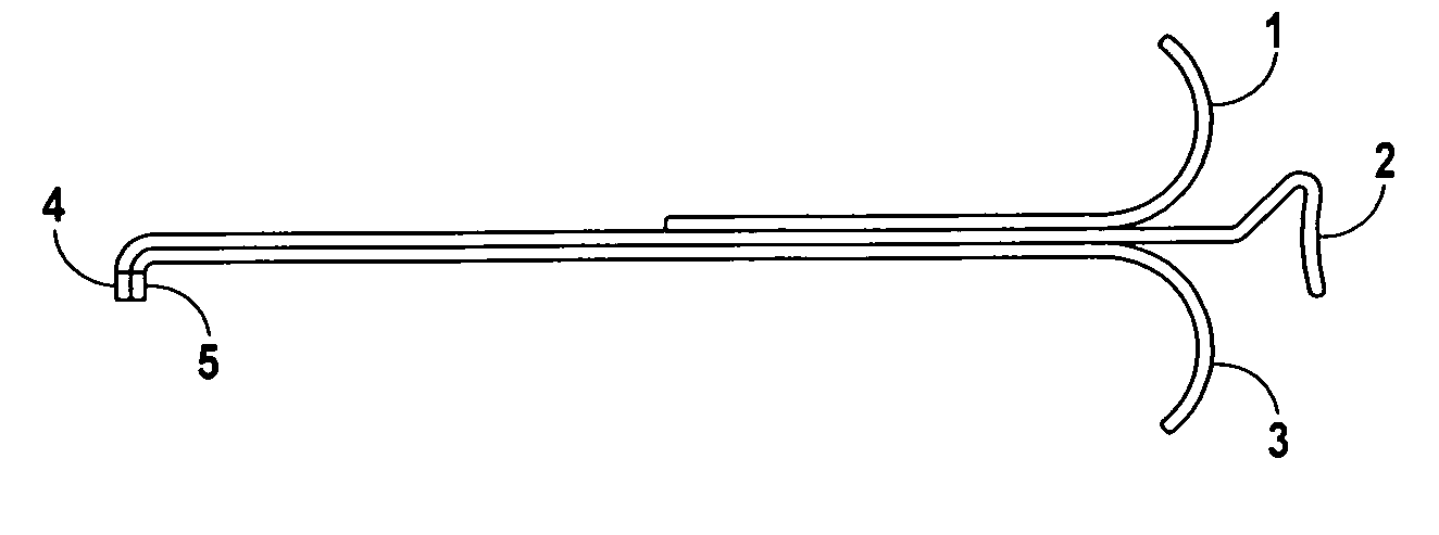
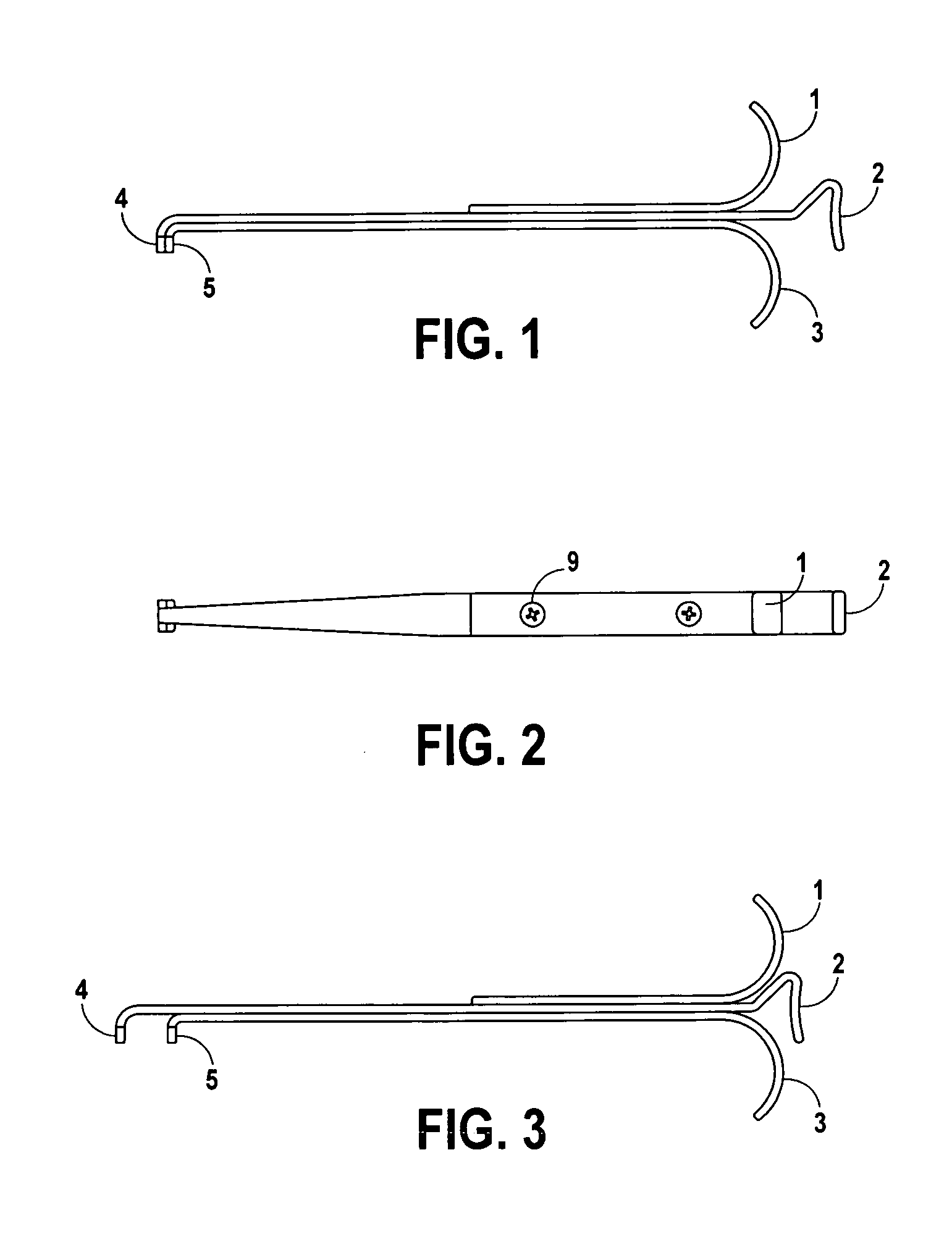
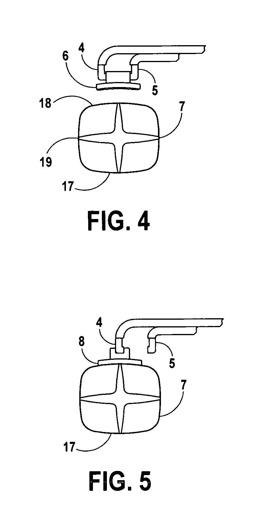
[0039]A Direct Bond Bracket Application Instrument is shown (FIG. 6), comprised of a finger support member 1, slidable member 2, and stationary member 3. A rear guide bushing 10 and forward guide bushing 15 engage a rear guide slot 13 (FIG. 7) and forward guide slot 14 to provide alignment and permit parallel linear motion. A spring 11 is nested in a spring aperture 12 and exerts a force to proximate the upper gripping jaw 4 (FIGS. 1, 3) to the lower gripping jaw 5. A rear screw 9 and a forward screw 16 join the aforementioned components into a functional assembly.
[0040]FIGS. 1 and 2 show the invention in a passive state with the gripping jaws closed by virtue of the spring force. To operate the instrument, a practitioner engages the stationary member and finger support members with the first and second fingers, and the slidable member with the opposing thumb, in a familiar hypodermic syringe style grasp. By exerting increased force upon the slidable member...
PUM
 Abstract
Description
Claims
Application Information
 - R&D
- Intellectual Property
- Life Sciences
- Materials
- Tech Scout
- Unparalleled Data Quality
- Higher Quality Content
- 60% Fewer Hallucinations
Browse by: Latest US Patents, China's latest patents, Technical Efficacy Thesaurus, Application Domain, Technology Topic, Popular Technical Reports.
© 2025 PatSnap. All rights reserved.Legal|Privacy policy|Modern Slavery Act Transparency Statement|Sitemap|About US| Contact US: help@patsnap.com


