
Communication system, server, control apparatus and communication apparatus

a communication system and control apparatus technology, applied in the field of communication systems, can solve the problem that the qos cannot be determined in the forward direction in the appropriate manner

Inactive Publication Date: 2008-12-18
HITACHI LTD
View PDF11 Cites 38 Cited by
  • Summary
  • Abstract
  • Description
  • Claims
  • Application Information

AI Technical Summary

Benefits of technology

[0010]As described above, in case of the conventional communication system, each of the MN and the PDSN use the TFT to identify each IP flow and employs a proper QoS for the IP flow in the RAN. This makes it possible for the conventional communication system to operate with no problems when the terminal uses the simple IP or mobile IPv4 protocol.

Problems solved by technology

Consequently, in the RAN, the QoS cannot be determined appropriately to any packets in the forward direction.
This has been a problem.

Method used


Image

  • Communication system, server, control apparatus and communication apparatus
  • Communication system, server, control apparatus and communication apparatus
  • Communication system, server, control apparatus and communication apparatus

Examples


first embodiment

[0046]In this first embodiment of the present invention, it is premised that a terminal takes the initiative in setting the subject RAN communication channel.

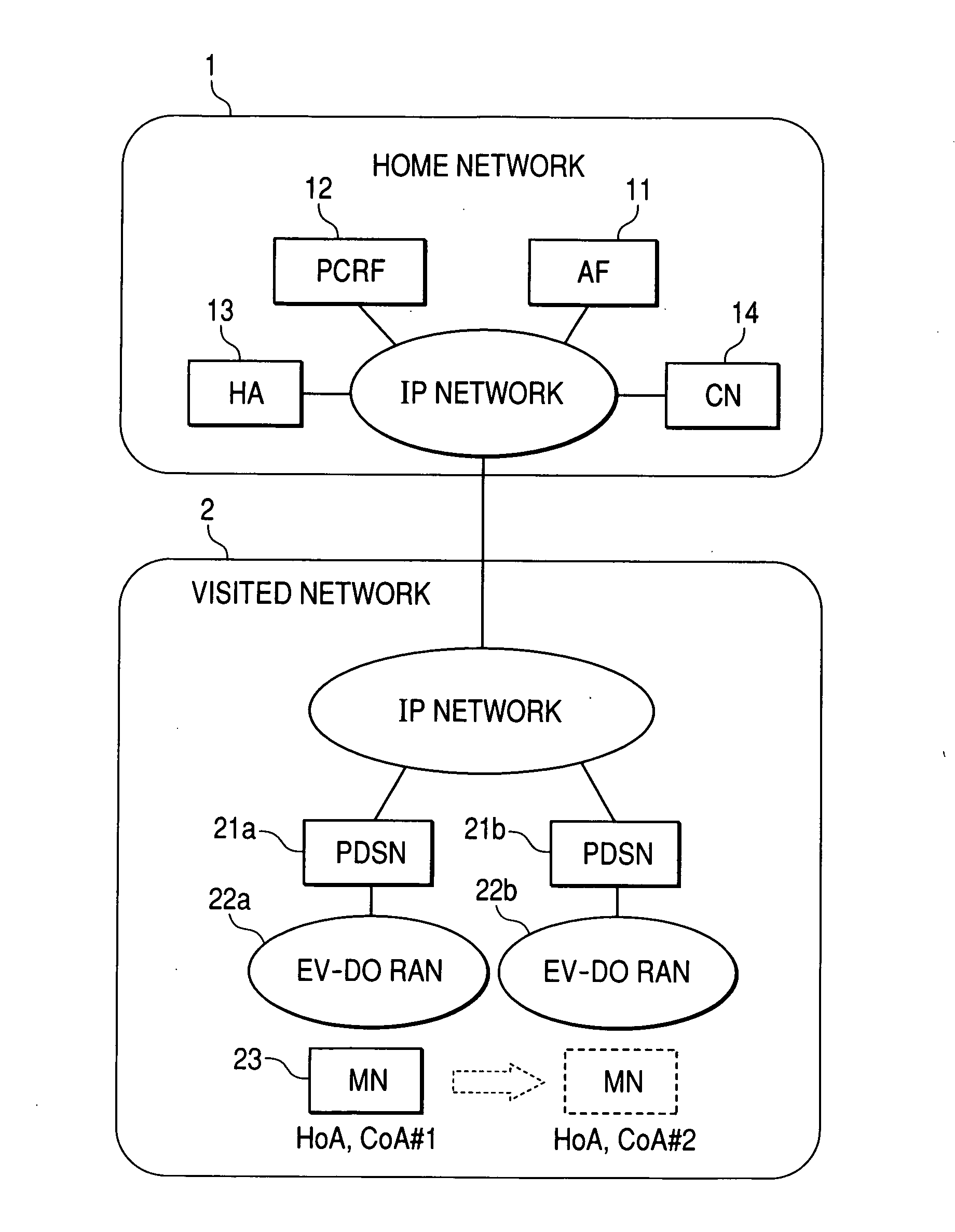
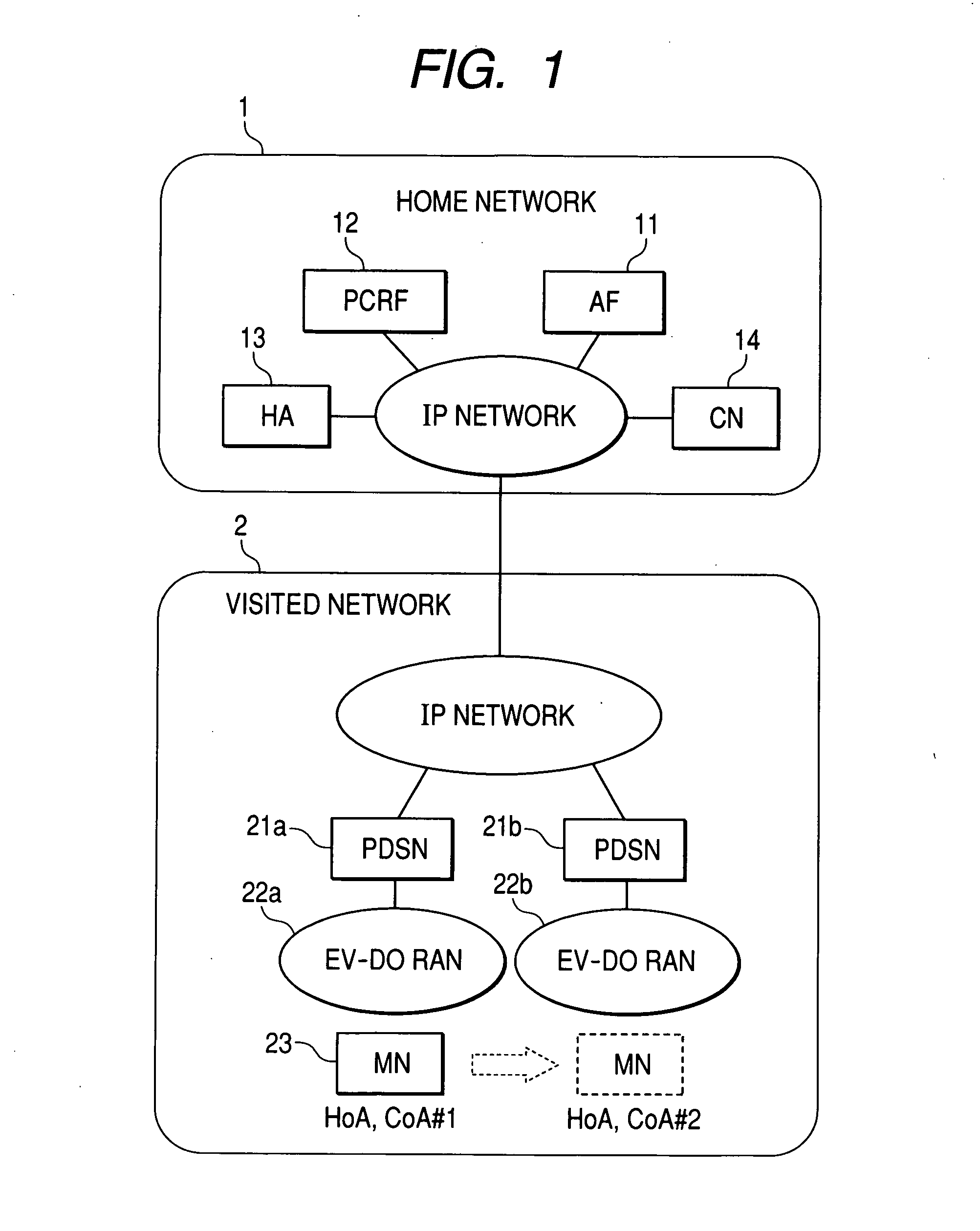
[0047]FIG. 1 shows a configuration example of a communication system of the present invention. The communication system consists of a home network 1 and a visited network 2. The home network 1 is connected to an AF 11 that controls services, a PCRF 12 that controls the QoS of the RAN, an HA 13 that controls mobile IPv6 communications, and a CN 14. The visited network 2 is connected to a PDSN (21a, 21b), an EV-D0 RAN (22a, 22b), and an MN 23, respectively.

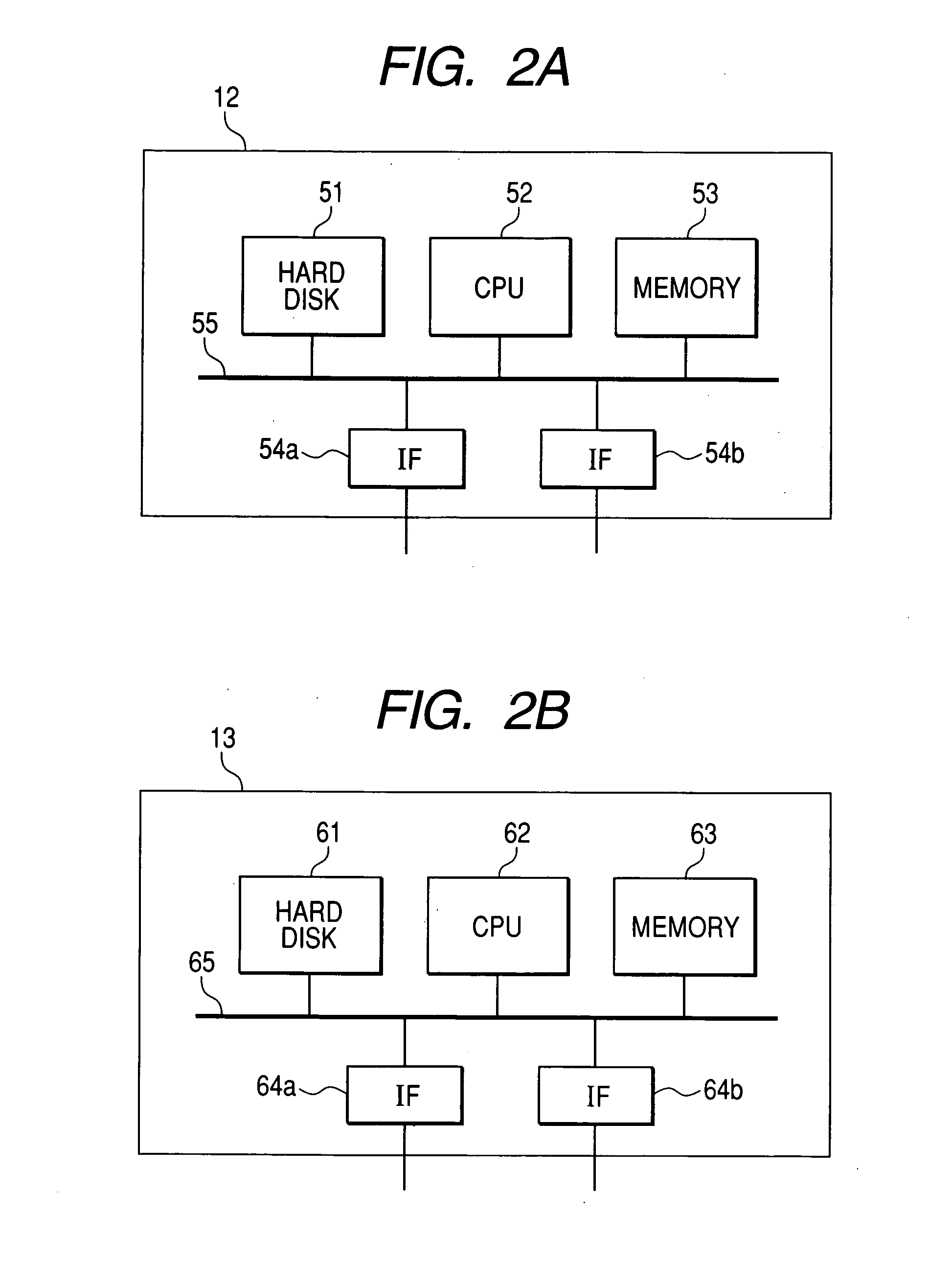
[0048]FIG. 2A shows a unit configuration of the PCRF 12. The PCRF 12 consists of a hard disk 51, a CPU 52, a memory 53, and an IF (54a, 54b). Those components of the PCRF 12 are connected to each another through a bus 55. Programs used to execute the functions of the PCRF 12 are stored in the memory 53 and the CPU 52 reads those programs sequentially to execute those functions....

second embodiment

[0082]In this second embodiment, it is premised that a network (PCRF 12) takes the initiative in setting the subject RAN communication channel.

[0083]The network configuration in this second embodiment is the same as that in the first embodiment. Except for the QoS profile table 440 shown in FIG. 25 provided in the PCRF 12, the system configuration is also the same as that in the first embodiment.

[0084]The QoS profile table 440 shown in FIG. 25 manages the QoS profile that each terminal can use in its communication range. The PCRF 12, provided with this table, comes to be able to determine QoS parameters appropriately to the object network condition upon starting a service. The QoS profile table 440 consists of fields of PPP Session ID 441 used to identify each PDSN and each PPP session uniquely, Terminal IP Address 442, and Bearer Information 443. The Bearer Information 443 consists of fields of Usage 443a (bearer usage), Priority 443b (priority level), and Bandwidth 443c (secured b...


PUM


Abstract

Disclosed herewith is a communication system, which can solve the following conventional problem that if packets exchanged between a terminal and an HA are encapsulated with use of the mobile IPv6 protocol, the PDSN cannot identify any IP flows in the mobile IPv6 tunnel. Consequently, there is no QoS usable appropriately to the services in the EV-D0 RAN. To solve such a problem, the PCRF notifies the HA of the filter information used to specify each IP flow and the flow label assigned to each IP flow. The HA then sets the flow label in the outer IPv6 header of the packet matching with the filter information and transfers the packet to the object unit. The PDSN then refers to the flow label set in the outer IPv6 header to identify the object IP flow in the mobile IPv6 tunnel. Consequently, a proper QoS can be usable for the services respectively in the EV-D0 RAN.

Description

CLAIM OF PRIORITY[0001]The present application claims priority from Japanese application JP 2007-158151 filed on Jun. 15, 2007, the content of which is hereby incorporated by reference into this application.FIELD OF THE INVENTION[0002]The present invention relates to a communication system that controls the QoS of an access network by linking the control with service controls. More particularly, the present invention relates to a mobile communication system that controls mobile communications with use of the mobile IPv6 protocol.BACKGROUND OF THE INVENTION[0003]The mobile IPv6 (refer to IETF RFC3775, Mobility Support in IPv6) is a protocol that enables communications even during moving from a network to another with use of the same IP address. The mobile IPv6 protocol uses networks, each of which includes a mobile node (MN) that enables communications during moving among plural networks, a home agent (HA) that manages position information of the MN, and a correspondent node (CN) tha...

Claims


Application Information

Patent Timeline
IPC IPC(8): H04B7/00H04L47/80H04W28/00H04W28/16H04W28/18H04W36/38H04W40/34H04W80/04
CPCH04L47/10H04W28/16H04W80/04
Inventor NAKAMURA, HITOMIMATSUMOTO, NORIHISAMORISHIGE, TAKEHIRONAKAHARA, NARUHITO
Owner HITACHI LTD
Learn More