
Noise filter

a noise filter and noise technology, applied in the field of noise filters, can solve the problems of low phase noise becoming an important issue, noise filter is not applicable to high frequency and multiple band systems, power dissipation of resonators,

Inactive Publication Date: 2008-12-18
RICHWAVE TECH CORP
View PDF12 Cites 15 Cited by
  • Summary
  • Abstract
  • Description
  • Claims
  • Application Information

AI Technical Summary

Problems solved by technology

To satisfy low power consumption and high signal to noise ratio in a communication system, low phase noise has become an important issue.
Accordingly, such a noise filter is not applicable to a high frequency and multiple band system.
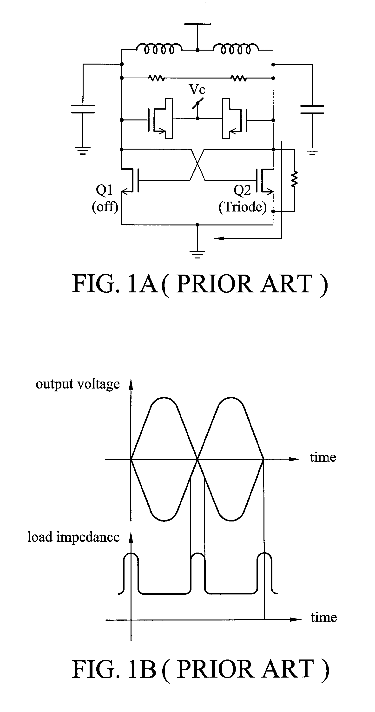
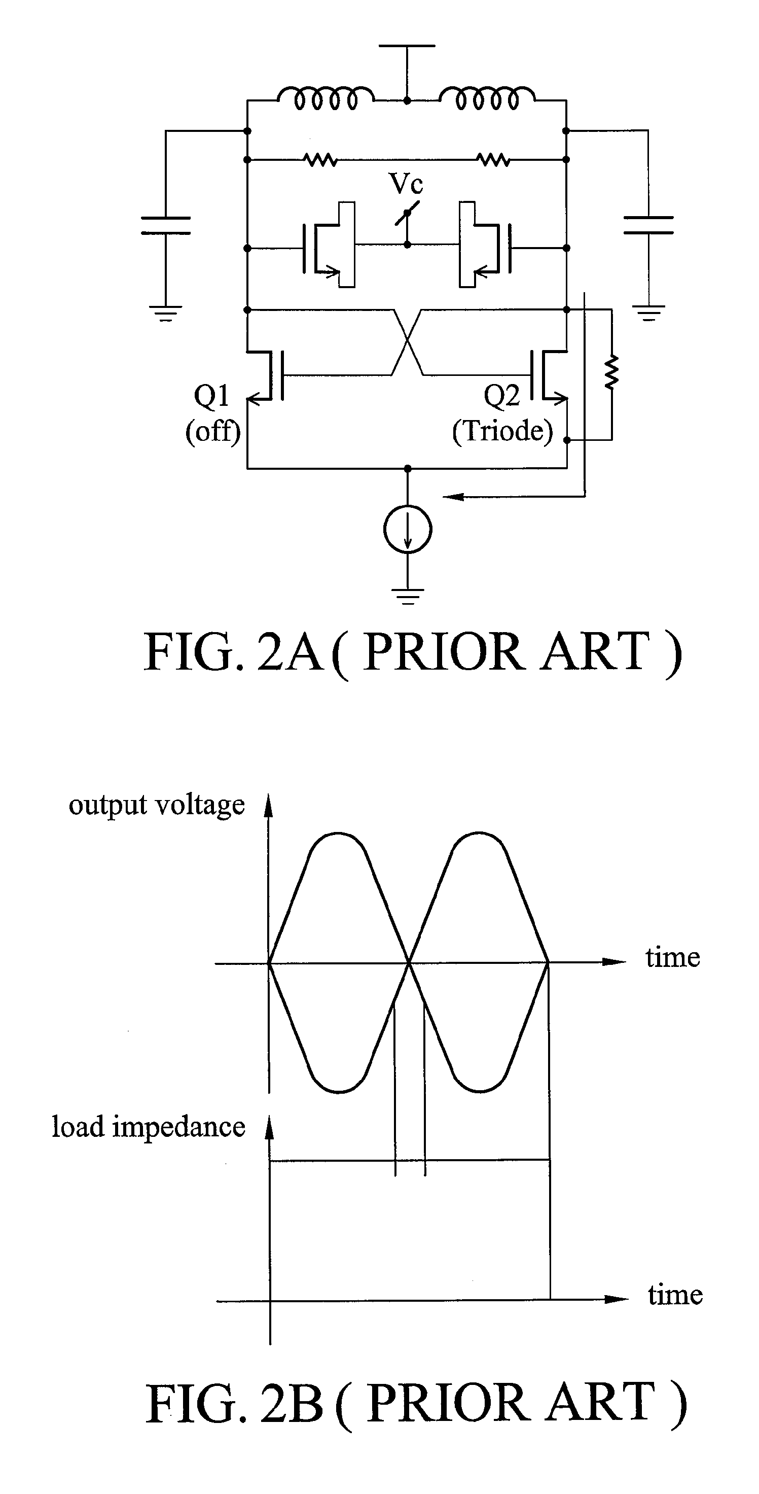
When the differential output voltage becomes higher, a channel resistance rds of the transistor Q2 operated in a triode region becomes lower and forms a current path to AC ground, resulting in power dissipation of the resonator.
An average impedance to ground in an oscillation cycle is thus lowered, leading to lower Q-factor of the resonator and higher phase noise of the oscillator.
In addition, such a low inductance and high Q-factor are not easily achieved by spiral inductors.
As a result, inductor characteristics and parasitic capacitance of the common source needs to be precisely controlled, or performance of the noise filter is limited.

Method used


Image

  • Noise filter
  • Noise filter
  • Noise filter

Examples


Embodiment Construction

[0028]The following description is the best-contemplated mode of carrying out the invention. This description is made for the purpose of illustrating the general principles of the invention and should not be taken in a limiting sense. The scope of the invention is best determined by reference to the appended claims.

[0029]FIG. 4 is a schematic diagram of a transmission line for describing impedance characteristics of a transmission line circuit. Input impedance Zin of a transmission line is typically defined as

Zin=Z0ZL+jZ0tanβlZ0+jZLtanβl,

wherein Z0 is characteristic impedance of a transmission line, Z0 is characteristic impedance of a transmission line, ZL is a load impedance and l is a length of the transmission line. When one end of the transmission line is grounded, i.e, the load impedance ZL is 0, the input impedance is simplified as Zin=jZ0 tan βl. When the length of the transmission line equals a quarter-wave length λ / 4, the input impedance becomes ∞, leading to a state of hig...


PUM


Abstract

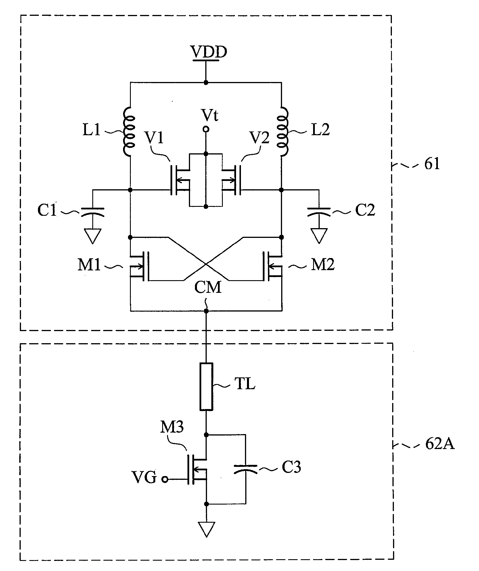
A noise filter connected to an LC oscillator is provided. The noise filter comprises a transmission line, a DC bias circuit, and a capacitor. The transmission line is connected to the LC oscillator. The DC bias circuit is connected to the transmission line and provides a bias current. The capacitor has one end connected between the transmission line and the DC bias circuit and the other end AC grounded and provides a path to AC ground to the transmission line. A length of the transmission line is odd times that of a quarter-wavelength of a secondary harmonic wave of the LC oscillator.

Description

BACKGROUND OF THE INVENTION[0001]1. Field of the Invention[0002]The invention relates to a noise filter and, in particular, to a noise filter with a transmission line to cancel noise thereof.[0003]2. Description of the Related Art[0004]An oscillator is typically a component of a receiver and performs frequency conversion in a communication system. Among all specifications of an oscillator, the most important item is phase noise. Phase noise directly influences signal to noise ratio of a receiver, adjacent channel rejection, bandwidth of a transmitter and so forth. With modern communication systems migrating to higher frequencies and multiple frequency bands to meet higher transmission rate requirements, a compatible low phase noise oscillator is playing a more important role in communication systems. In integrated circuits, an oscillator is typically constructed with cross-coupled LC tanks, also known as a differential LC oscillator. The oscillator has lower phase noise when compare...

Claims


Application Information

Patent Timeline
Patent Type & Authority Applications(United States)
IPC IPC(8): H01P1/20
CPCH03B5/18H03H7/0123H03H2250/00H01P1/20363H03B5/1228H03B5/1212H03B5/1215H03B5/1253
Inventor WU, HAN-HAO
Owner RICHWAVE TECH CORP
Learn More