Eureka AIR delivers breakthrough ideas for toughest innovation challenges, trusted by R&D personnel around the world.

Magneto-radar detector and method

a magneto-radar and detector technology, applied in the field of magneto-radar detectors and methods, can solve the problems of inconvenient use, no prior art radar systems disclose a tuned radar system, and formidable limitation of long-range operation, and achieve the effect of cost-effectiveness

Active Publication Date: 2005-07-05
LAWRENCE LIVERMORE NAT SECURITY LLC
View PDF18 Cites 142 Cited by
  • Summary
  • Abstract
  • Description
  • Claims
  • Application Information

AI Technical Summary

Benefits of technology

[0013]Accordingly, the present system and method provides a desired portable, cost effective, non-invasive arrangement, capable of detecting objects in a variety of commercial and non-commercial applications.

Problems solved by technology

Since the magnetic field must travel out to the object and then couple back to the loop, a sixth order decrease in signal strength versus range results, forming a formidable limitation to long range operation.
None of the prior art radar systems disclose a radar system tuned for optimal sensitivity of magnetically excited metal objects.

Method used


Image

  • Magneto-radar detector and method
  • Magneto-radar detector and method
  • Magneto-radar detector and method

Examples


Embodiment Construction

[0020]Referring now to the drawings, specific embodiments of the invention are shown. The detailed description of the specific embodiments, together with the general description of the invention, serves to explain the principles of the invention.

[0021]Unless otherwise indicated, all numbers expressing quantities of ingredients, constituents, reaction conditions and so forth used in the specification and claims are to be understood as being modified in all instances by the term “about”. Accordingly, unless indicated to the contrary, the numerical parameters set forth in the specification and attached claims are approximations that may vary depending upon the desired properties sought to be obtained by the subject matter presented herein. At the very least, and not as an attempt to limit the application of the doctrine of equivalents to the scope of the claims, each numerical parameter should at least be construed in light of the number of reported significant digits and by applying o...


PUM


Abstract

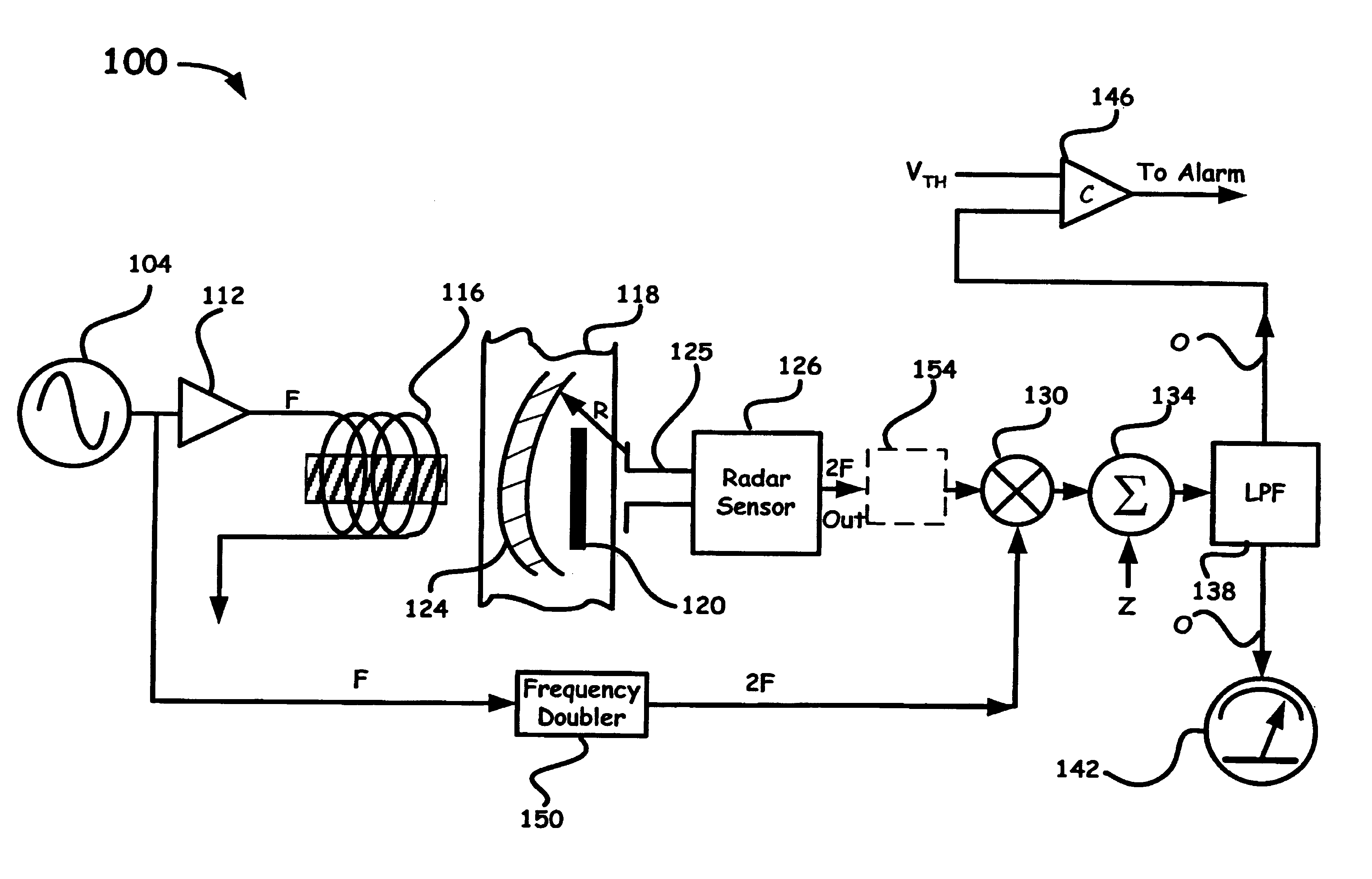
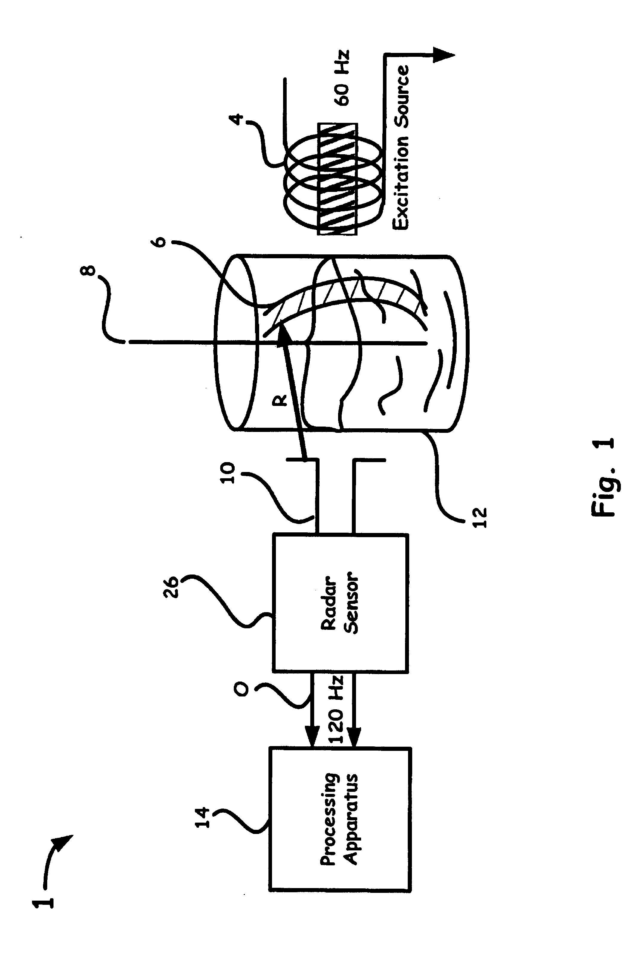
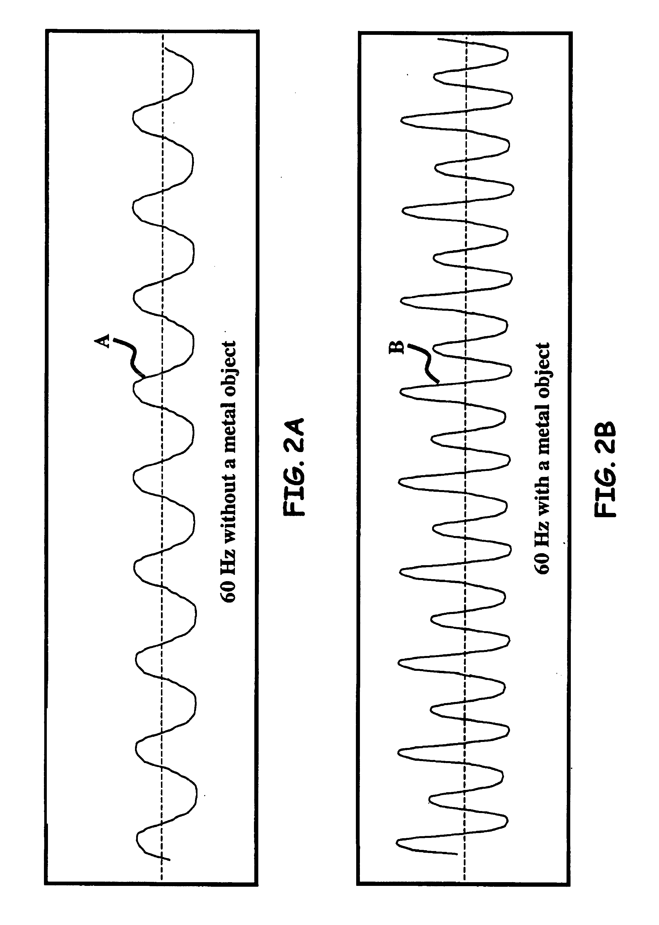
A varying magnetic field excites slight vibrations in an object and a radar sensor detects the vibrations at a harmonic of the excitation frequency. The synergy of the magnetic excitation and radar detection provides increased detection range compared to conventional magnetic metal detectors. The radar rejects background clutter by responding only to reflecting objects that are vibrating at a harmonic excitation field, thereby significantly improving detection reliability. As an exemplary arrangement, an ultra-wideband micropower impulse radar (MIR) is capable of being employed to provide superior materials penetration while providing range information. The magneto-radar may be applied to pre-screening magnetic resonance imaging (MRI) patients, landmine detection and finding hidden treasures.

Description

[0001]The United States Government has rights in this invention pursuant to Contract No. W-7405-ENG-48 between the United States Department of Energy and the University of California for the operation of Lawrence Livermore National Laboratory.BACKGROUND OF THE INVENTION[0002]1. Field of the Invention[0003]The present invention relates to radar systems and methods, and more particularly to a method employing radar to locate a magnetically excited object.[0004]2. Description of Related Art[0005]Electronic detection of metal objects, particularly hidden metal objects, traditionally involves a “metal detector” that includes an electromagnetic loop coupled to an oscillator and detector. When the loop is placed near a metal object, its inductance changes and produces a change in the oscillator's frequency, which is detected. Modern versions of this technique employ pulse methods. In either case, detection range is sharply limited by a third power decrease in magnetic field strength versus...

Claims


Application Information

Patent Timeline
Patent Type & Authority Patents(United States)
IPC IPC(8): G01S13/00G01S13/02G01S13/04G01S13/56G01S13/86
CPCG01S13/0209G01S13/04G01S13/56G01S13/86
Inventor MCEWAN, THOMAS E.
Owner LAWRENCE LIVERMORE NAT SECURITY LLC
Why Eureka
Eureka Blog
Learn More