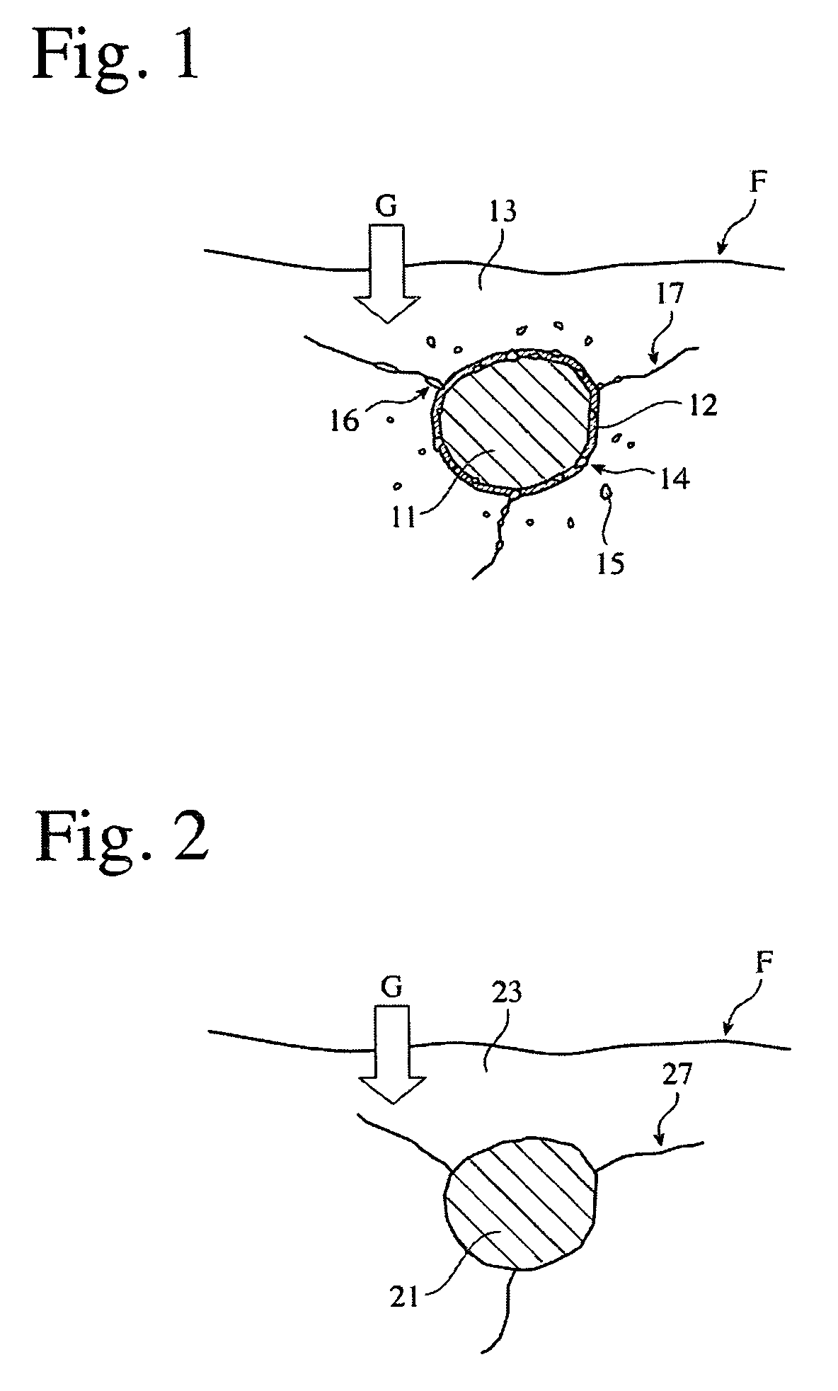
Heat-Resistant Cast Iron And Exhaust Equipment Member Formed Thereby
- Summary
- Abstract
- Description
- Claims
- Application Information
AI Technical Summary
Benefits of technology
Problems solved by technology
Method used
Image


Examples
examples 1-74
, COMPARATIVE EXAMPLES 1-16, AND CONVENTIONAL EXAMPLES 1-6
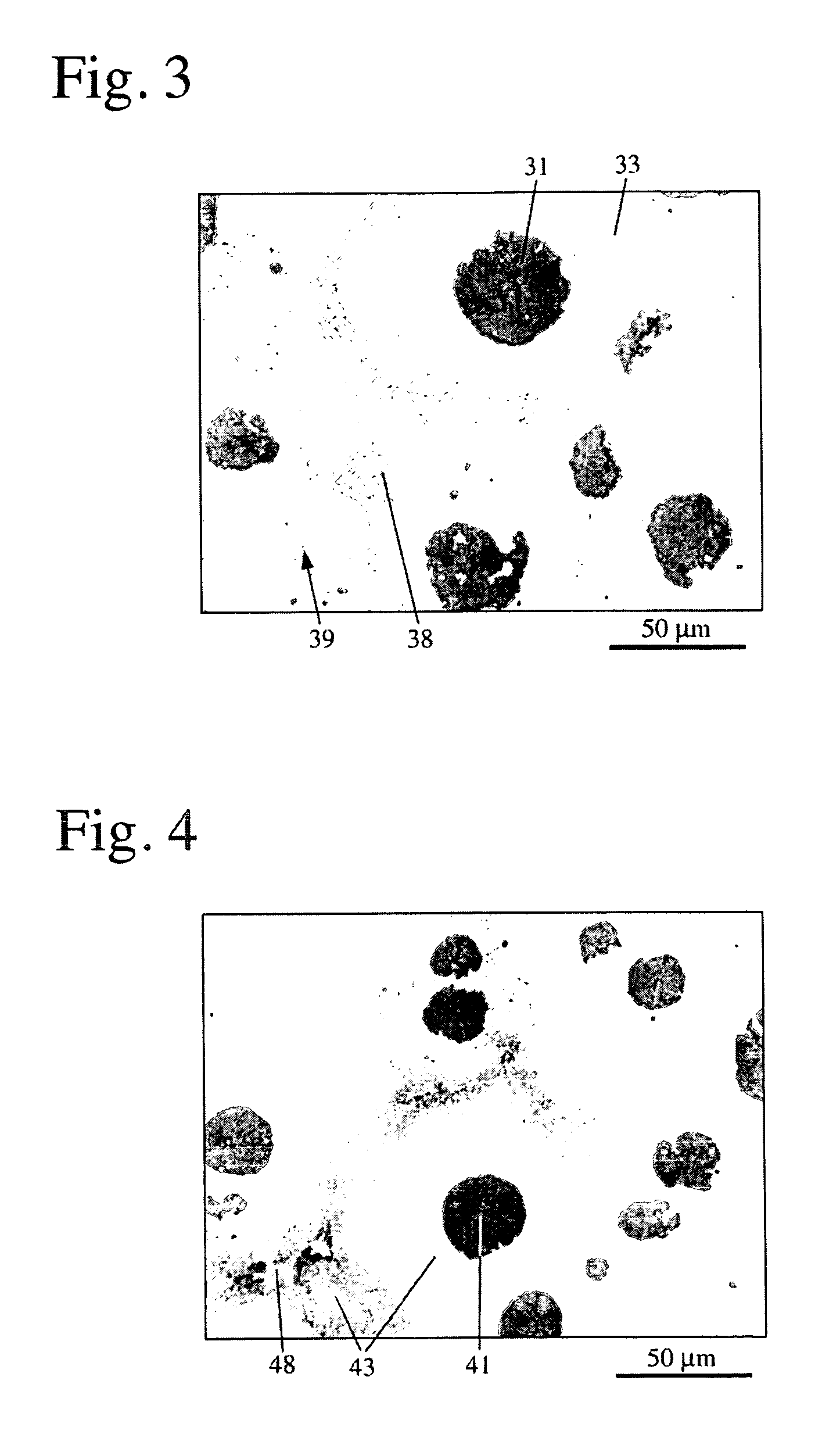
[0130]Each cast iron having a chemical composition (% by weight) shown in Table 1 was melted in an SiO2-lined, 100-kg, high-frequency furnace in the air, tapped from the furnace at 1450° C. or higher, and spheroidized by a sandwiching method using commercially available Fe—Si—Mg. Immediately thereafter, it was poured at 1300° C. or higher into a Y-block mold. After shake-out, each sample was shot-blasted, and annealed for ferritization by keeping it at a temperature of 600-940° C. as shown in Table 2 for 3 hours, and then cooling it in the furnace. Incidentally, no heat treatment was conducted on the samples of Example 9, Comparative Examples 1 and 9, and Conventional Examples 1, 2 and 4, and annealing for ferritization was conducted not by furnace-cooling but by air-cooling in the sample of Comparative Example 2. The samples of Conventional Examples 5 and 6 were spheroidized by a sandwiching method using commercially availab...
example 1
CONVENTIONAL EXAMPLE 1
[0132]FCD450 of JIS.
example 2
CONVENTIONAL EXAMPLE 2
[0133]Mo-containing, high-Si, spheroidal graphite cast iron (Hi-SiMo).
PUM
| Property | Measurement | Unit |
|---|---|---|
| Temperature | aaaaa | aaaaa |
| Temperature | aaaaa | aaaaa |
| Temperature | aaaaa | aaaaa |
Abstract
Description
Claims
Application Information
 - R&D
- Intellectual Property
- Life Sciences
- Materials
- Tech Scout
- Unparalleled Data Quality
- Higher Quality Content
- 60% Fewer Hallucinations
Browse by: Latest US Patents, China's latest patents, Technical Efficacy Thesaurus, Application Domain, Technology Topic, Popular Technical Reports.
© 2025 PatSnap. All rights reserved.Legal|Privacy policy|Modern Slavery Act Transparency Statement|Sitemap|About US| Contact US: help@patsnap.com