
Production method of spindle motor and spindle motor

Inactive Publication Date: 2008-12-11
NIDEC CORP
View PDF5 Cites 1 Cited by
  • Summary
  • Abstract
  • Description
  • Claims
  • Application Information

AI Technical Summary

Benefits of technology

[0014]According to one aspect of the present invention, the cutting is performed for the disc-support member of lower cutting resistance than that of the hub member, thereby obtaining the first contact face which is in contact with the flat portion of the disc and the second contact face which is in contact with the inner circumferential portion of the disc. In this way, the damage of the cutting tool due to the cutting resistance can be suppressed, and the first contact face and the second contact face can be obtained in a short time. Accordingly, the manufacturing cost of the spindle motor can be reduced.
[0019]According to another aspect of the present invention, the disc-support member is made from a material having a lower cutting resistance than that of the material from which the hub member is made. For this reason, the damage of a cutting tool due to the cutting resistance can be suppressed, and the cutting can be performed for the base portion and the positioning portion in a short time. Accordingly, the manufacturing cost of the spindle motor can be reduced, and the productivity of the spindle motor can be improved.

Problems solved by technology

However, the cutting for the entire shape of the hub member 923 increases the working cost of the hub member 923, which prevents spindle motors from being manufactured at a low cost.
In addition, the cutting is conventionally performed for the metal material of high cutting resistance, so that a cutting tool wears out in a relatively shorter time, and it is difficult to shorten the working time.
These factors further increase the manufacturing cost of the spindle motors and deteriorate the productivity.

Method used


Image

  • Production method of spindle motor and spindle motor
  • Production method of spindle motor and spindle motor
  • Production method of spindle motor and spindle motor

Examples


Embodiment Construction

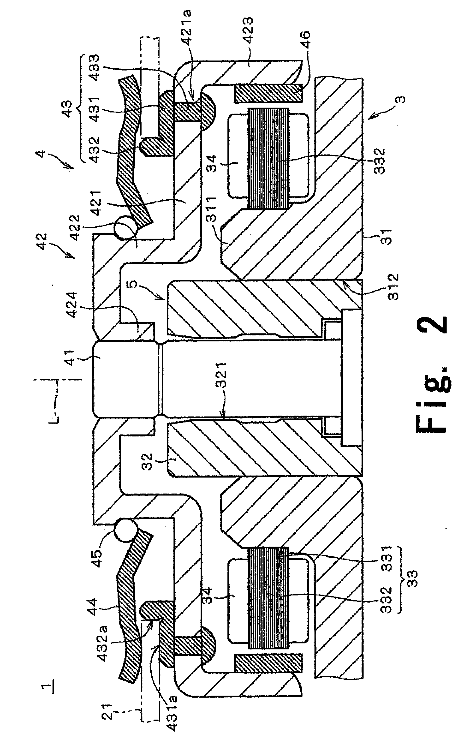
[0037]Referring to FIGS. 1 through 15, preferred embodiments of the present invention will be described in detail. It should be noted that in the explanation of the present invention, when positional relationships among and orientations of the different components are described as being up / down or left / right, ultimately positional relationships and orientations that are in the drawings are indicated; positional relationships among and orientations of the components once having been assembled into an actual device are not indicated. Meanwhile, in the following description, an axial direction indicates a direction parallel to a rotation axis, and a radial direction indicates a direction perpendicular to the rotation axis.

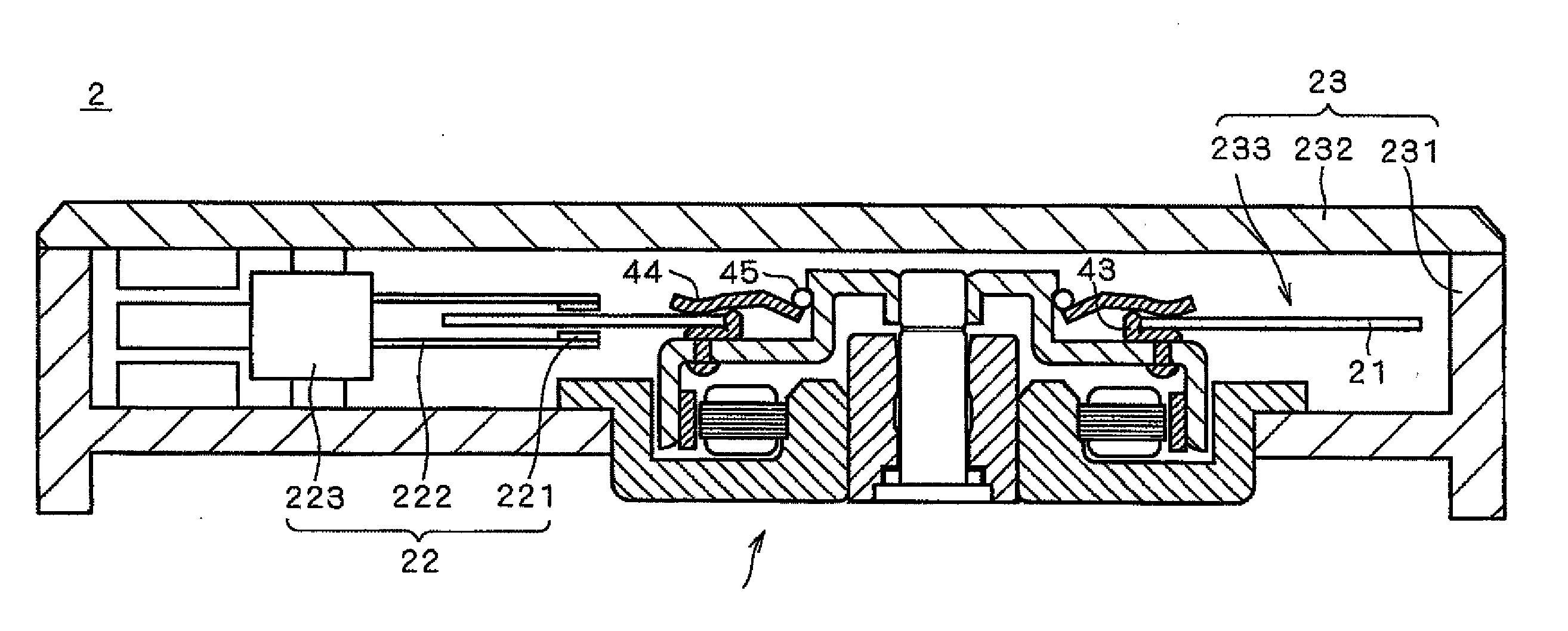
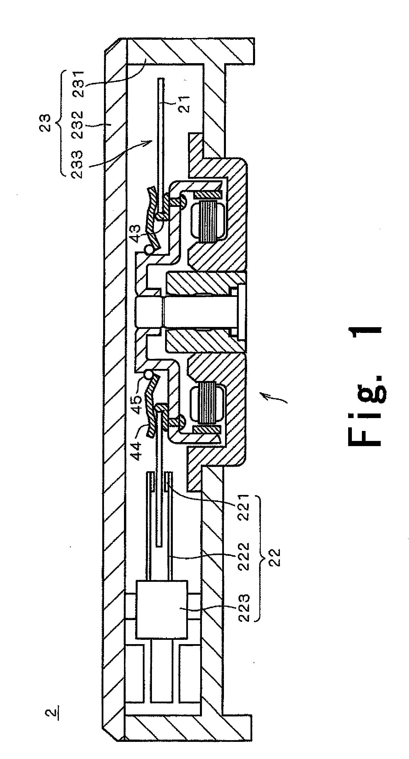
[0038]FIG. 1 is a sectional view of a disk driver 2 furnished with a disc-driving spindle motor 1 according to one preferred embodiment of the present invention taken along a plane including a center axis. The disk driver 2 is a hard-disk driver for reading and writin...


PUM

PropertyMeasurementUnit
Electrical resistanceaaaaaaaaaa
Speedaaaaaaaaaa

Abstract

In a manufacturing method of a disk-driving spindle motor, a disc-support member includes a base portion and a positioning portion. The disc-support member is fixed to a hub member. The base portion is in contact with a lower surface of a disc. The positioning portion extends axially upwardly from the base portion, and is disposed around the center axis. The positioning portion is in contact with an inner circumferential face or an inner circumferential rim of the disc.The disc-support member is preferably made from a resin material having a cutting resistance smaller than that of a metal material from which the hub member is made.

Description

BACKGROUND OF THE INVENTION[0001]1. Field of the Invention[0002]The present invention relates to a manufacturing method of a disk-driving spindle motor for rotating a disc such as a magnetic disc or an optical disk, and a spindle motor manufactured by the manufacturing method.[0003]2. Description of the Related Art[0004]A spindle motor for rotating a magnetic disc is mounted on a hard disk drive used in a personal computer, a car navigation, or the like.[0005]FIG. 16 is a sectional view of an exemplary configuration of a conventional spindle motor taken along a plane including a center axis. As shown in FIG. 16, a conventional spindle motor 9 includes a stationary section 91 having a stator core 911 and a coil 912, and a rotor 92 having a rotor magnet 921. The spindle motor 9 generates torque by the action of a magnetic flux between the stator core 911 and the coil 912, and the rotor magnet 921, thereby rotating the rotor 92 about a center axis L.[0006]The rotor 92 of the spindle mo...

Claims


Application Information

Patent Timeline
IPC IPC(8): G11B17/03B32B38/04
CPCY10T156/1052G11B17/0287
Inventor GOMYO, MASATOSEKII, YOICHISAITO, KAZUYOSHIHASEGAWA, TADASHIKATO, TSUYOSHI
Owner NIDEC CORP
Learn More