
Miniature sub-resonant multi-band vhf-uhf antenna

a sub-resonant, multi-band technology, applied in the direction of modulation, transmission, amplitude modulation, etc., can solve the problems of low efficiency of antennas, trade-off between antenna size and efficiency, etc., and achieve the effect of low cos

Inactive Publication Date: 2008-12-11
VISHAY INTERTECHNOLOGY INC
View PDF44 Cites 126 Cited by
  • Summary
  • Abstract
  • Description
  • Claims
  • Application Information

AI Technical Summary

Benefits of technology

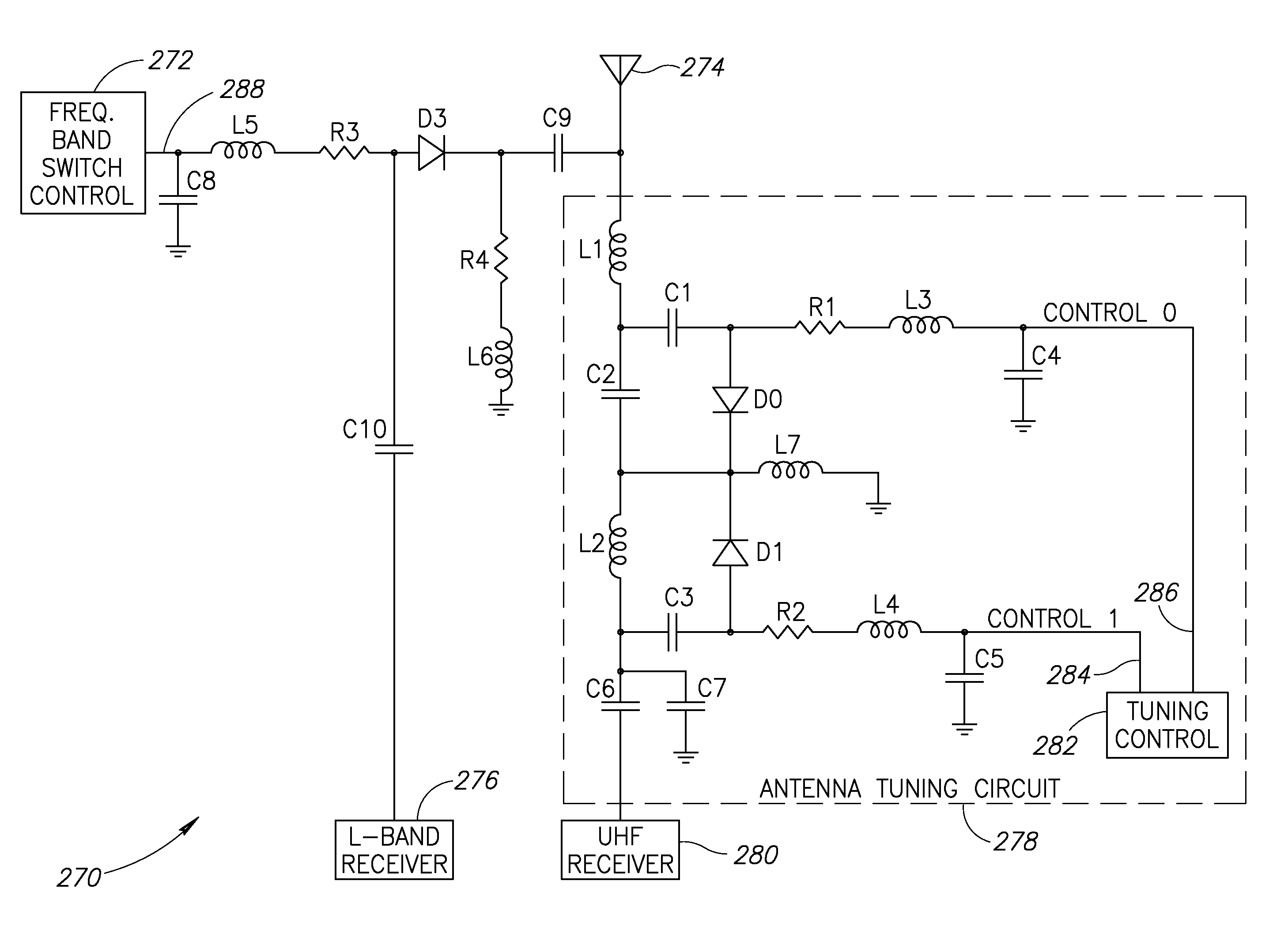
[0016]The present invention is a novel antenna system for receiving transmissions in the VHF and UHF frequency bands that overcomes the disadvantages and drawbacks of prior art antenna systems. The antenna system of the present invention is particularly suitable to provide a miniaturized antenna for UHF reception in mobile devices. The miniature antenna system of the present invention enables the implementation of low cost, small form factor mobile devices such as those designed to receive digital video broadcasting transmissions.
[0021]The use of the antenna system of the present invention provides numerous advantages, including the following: (1) the ability to cover the entire desired frequency band (e.g., VHF, UHF, L-band, etc.); (2) miniature size physical dimensions allowing the antenna system to fit into small form factor wireless mobile devices; and (3) the ability to tune to multiple frequency bands utilizing a bypass switch and appropriate antenna element and tuning circuit design.

Problems solved by technology

A disadvantage is that the antenna efficiency is reduced.
Thus, there is a tradeoff between antenna size and efficiency.

Method used


Image

  • Miniature sub-resonant multi-band vhf-uhf antenna
  • Miniature sub-resonant multi-band vhf-uhf antenna
  • Miniature sub-resonant multi-band vhf-uhf antenna

Examples


Embodiment Construction

Notation Used Throughout

[0049]The following notation is used throughout this document.

TermDefinitionACAlternating CurrentASICApplication Specific Integrated CircuitAVIAudio Video InterleaveBMPWindows BitmapBWABroadband Wireless AccessCOFDMCoded OFDMCPUCentral Processing UnitDCDirect CurrentDEDielectric LossesDSLDigital Subscriber LineDVB-HDigital Video Broadcasting-HandheldDVB-TDigital Video Broadcasting-TerrestrialEDGEEnhanced Data Rates for GSM EvolutionFMFrequency ModulationFPGAField Programmable Gate ArrayGPRSGeneral Packet Radio ServiceGPSGlobal Positioning SystemGSMGlobal System for Mobile communicationsICIntegrated CircuitIEEEInstitute of Electrical and Electronics EngineersIRInfraredJPGJoint Photographic Experts GroupLANLocal Area NetworkMBOAMultiband OFDM AllianceMBRAIMobile and Portable DVB-T / H Radio AccessInterfaceMP3MPEG-1 Audio Layer 3MPGMoving Picture Experts GroupOFDMOrthogonal Frequency Division MultiplexingOFDMOrthogonal Frequency Division MultiplexingPCPersonal Com...


PUM


Abstract

A novel antenna system for receiving transmissions in the VHF and UHF frequency bands particularly suitable as a miniaturized antenna for UHF reception, such as of digital video broadcasting transmissions. The antenna system utilizes a combination of three techniques including (1) the use of dialect loading using a high dielectric constant ceramic substrate; (2) an antenna dielectrically loaded and tuned to a significantly higher frequency than desired; and (3) use of a tuning circuit to compensate for the frequency offset of the antenna thereby shifting the resonant frequency to cover the entire band. The antenna is intentionally designed to be too small to radiate at the frequency of interest. The antenna element is then ‘forced’ to be tuned to the desired lower frequency using passive (or active) reactive components as part of a tuning circuit. Multi-band operation is achieved by providing a bypass switch to connect the antenna element either to (1) a first receiver without the tuning circuit (i.e. high frequency tuning) or (2) a second receiver with the tuning circuit (i.e. low frequency tuning).

Description

REFERENCE TO PRIORITY APPLICATION[0001]This application claims priority to U.S. Provisional Application Ser. No. 60 / 942,544, filed Jun. 7, 2007, entitled “Antenna system for UHF frequency band,” incorporated herein by reference in its entirety.FIELD OF THE INVENTION[0002]The present invention relates generally to antenna circuits and systems and more particularly relates to a miniature sub-resonant multi-band antenna system for the VHF-UHF frequency hand.BACKGROUND OF THE INVENTION[0003]As the use of computers and especially handheld or mobile electronic devices continues to increase at a rapid rate, the demand for peripherals and systems connected via wireless connections continues to increase. The number of wireless applications is currently increasing at a very high rate in areas such as security alarms, networking, personal computing, data communications, telephony and computer security.[0004]Wireless communications currently may take many forms such as ultrasonic, IR and RF. In...

Claims


Application Information

Patent Timeline
Patent Type & Authority Applications(United States)
IPC IPC(8): H04B1/40H01Q9/00
CPCH01Q9/0485H01Q9/0442
Inventor ALON, DANIBEN-BASSAT, DAVID
Owner VISHAY INTERTECHNOLOGY INC
Learn More