
Audio clock regenerator with precisely tracking mechanism

Active Publication Date: 2008-12-04
HIMAX TECH LTD
View PDF21 Cites 29 Cited by
  • Summary
  • Abstract
  • Description
  • Claims
  • Application Information

AI Technical Summary

Benefits of technology

[0014]The frequency of the crystal clock may be adjusted by the tracking circuit. The frequency may be adjusted when the cycle parameter is less or greater than the recovery parameter. In order to o

Problems solved by technology

It is commonly known to a person in the art that transmitting signals in analog waveforms comes with noise.
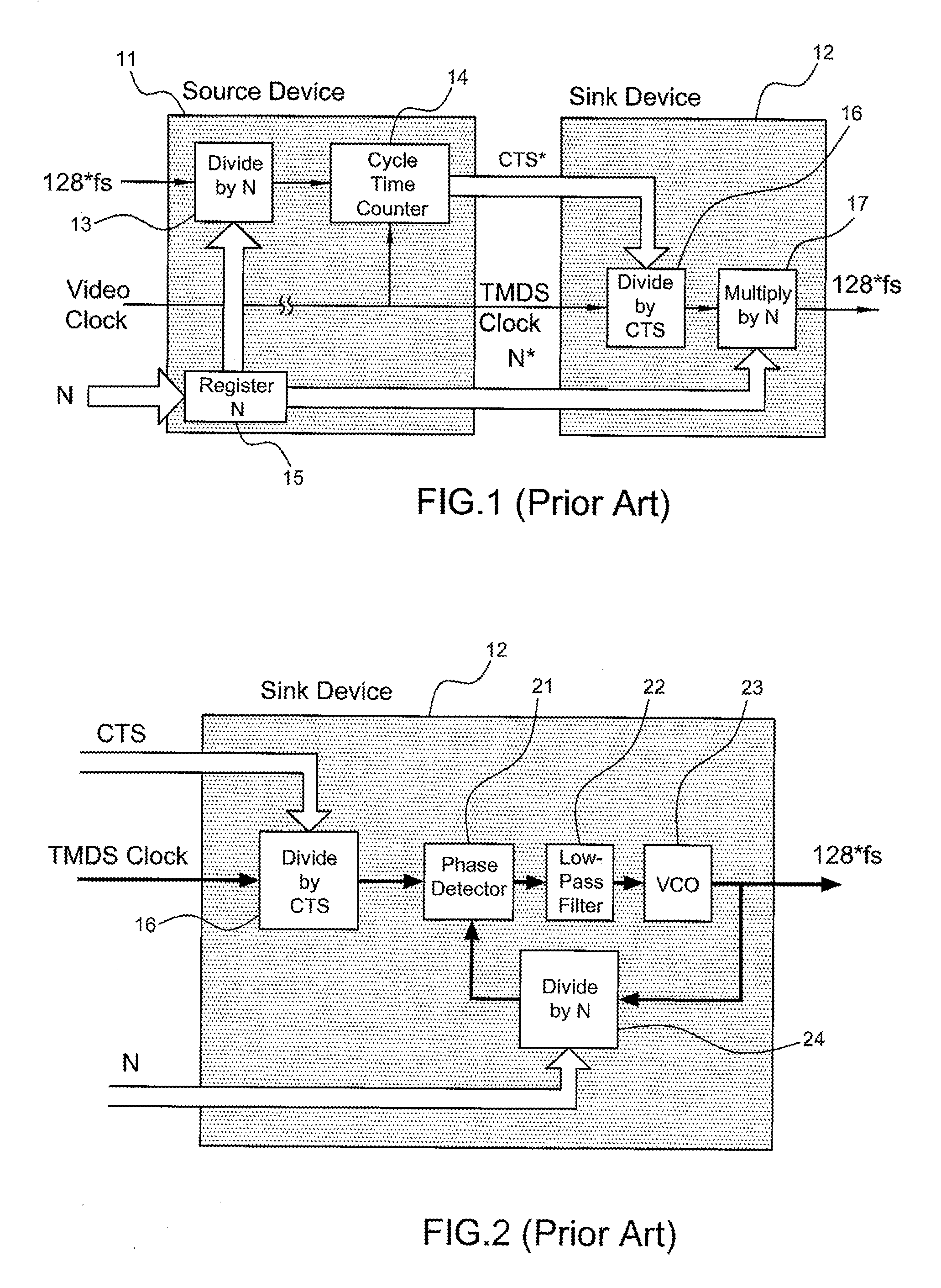
Although the HDMI Specification recommended several N and CTS values, it is still hard to obtain an audio clock with low jitter.
Thus, the accurate requirement 1000 ppm of the HDMI specification can not be easily achieved because the phase lock loop circuit can only adjust its phase slowly and noise may accumulate, either externally or internally, during this 1 ms waiting time.
The optional implementation of the clock recovery circuit in the sink device 12 according to the HDMI specification does not provide a low jitter clock recovery circuit.

Method used


Image

  • Audio clock regenerator with precisely tracking mechanism
  • Audio clock regenerator with precisely tracking mechanism
  • Audio clock regenerator with precisely tracking mechanism

Examples


Embodiment Construction

[0024]The present invention provides a method and apparatus to precisely track a clock input and to regenerate a recovered clock output in a data transmission system.

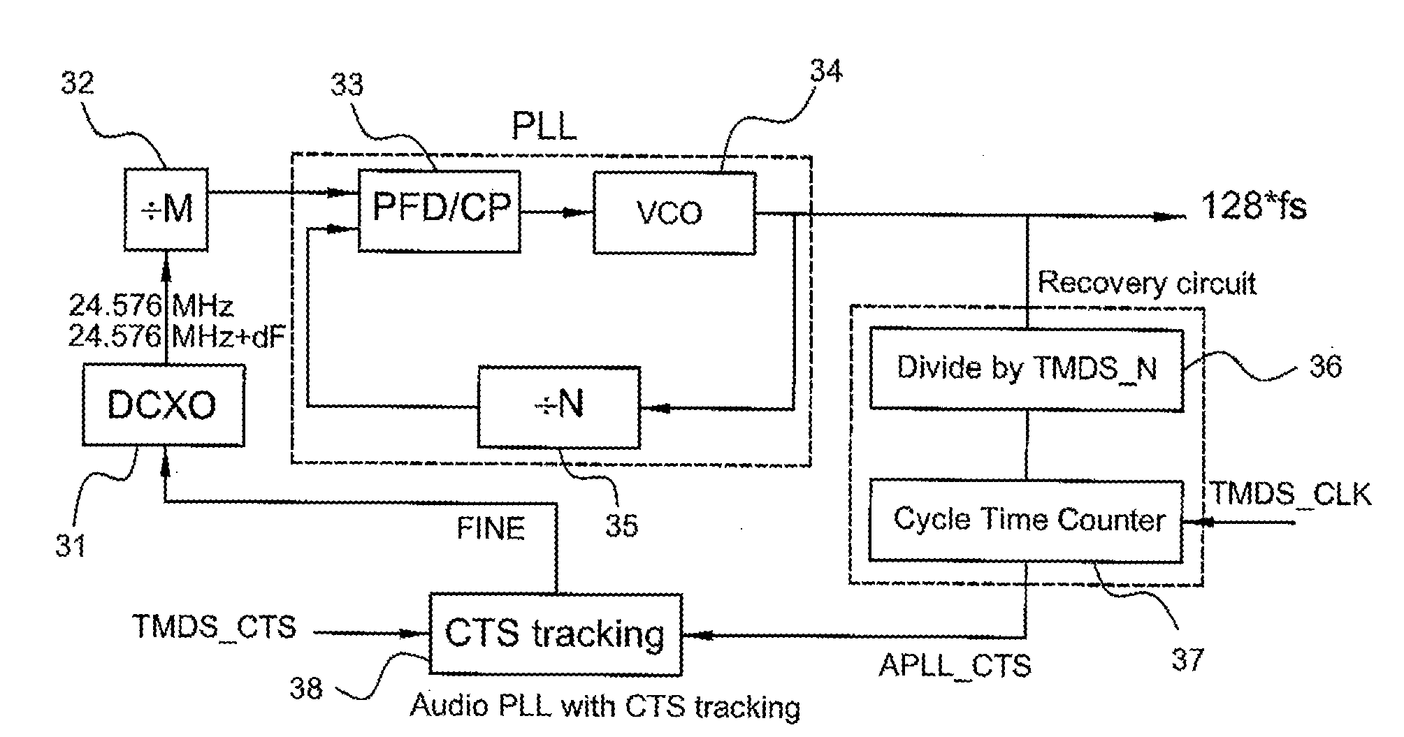
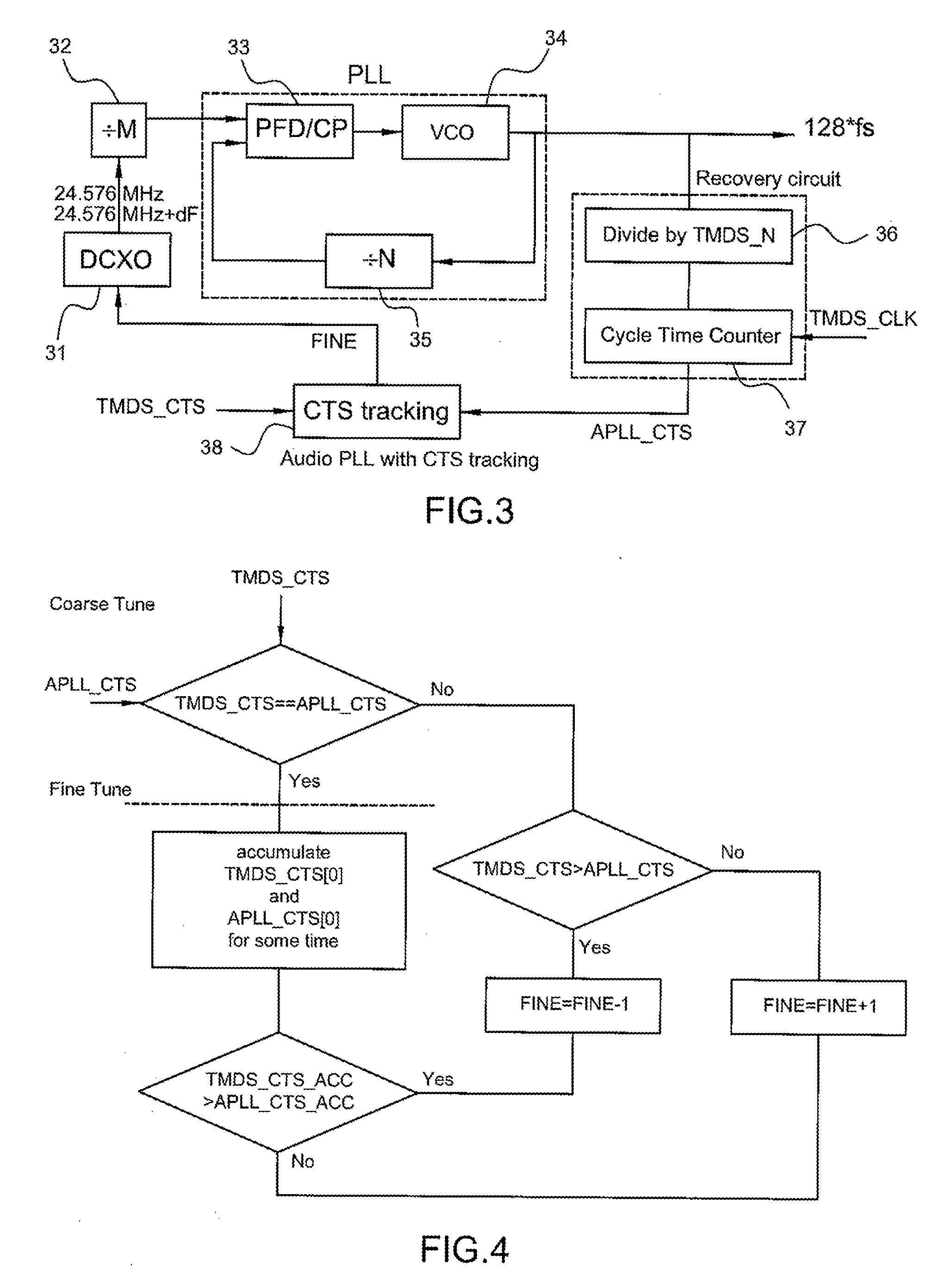
[0025]FIG. 3 illustrates an audio clock generator that recovers an audio clock (128*Fs) from a video clock TMDS_CLK with parameters TMDS_CTS and N according to one embodiment of the present invention. The audio clock regenerator comprises a phase lock loop circuit, a recovery circuit, a crystal oscillator 31 and a tracking circuit 38. The crystal oscillator 31 generates a crystal clock. For example, the crystal clock is 24.576 MHz. The generated crystal clock can be adjusted within a frequency range. In one embodiment, the crystal oscillator 31 may also be a digital controlled crystal oscillator. The crystal oscillator 31 may be an analog controlled crystal oscillator, for example, a voltage controlled crystal oscillator.

[0026]The clock regenerator further comprises a clock divider 32. The clock divider 32 divides the c...


PUM


Abstract

In an HDMI system, the clock regenerator proposed by the HDMI specification may suffer external noise because the input clock of a phase lock loop circuit in a sink device of the HDMI system is too slow. This slow input clock causes the phase lock loop circuit unable to adjust and reduce the jitter of an audio clock regenerated in the sink device. Therefore, one embodiment of the present invention provides a clock regenerator to extract the relationship between the regenerated audio clock and a video clock received by the sink device from other source devices. The clock regenerator may comprise a phase lock loop circuit, a recovery circuit, a crystal oscillator and a tracking circuit. The crystal oscillator generates a crystal clock. The phase lock loop circuit receives the crystal clock and regenerates an audio clock. The recovery circuit extracts the relationship between the audio clock and the received video clock. The tracking circuit tunes the frequency of the crystal clock based on the extracted relationship.

Description

FIELD OF THE INVENTION[0001]This invention relates to a clock regenerator in a digital transmission system, and more particularly, to a clock recovery circuit with a phase lock loop circuit.BACKGROUND OF THE INVENTION[0002]There are many standards available for data transmission in home use apparatuses. For example, an RF cable is used to transmit TV signals from an antenna to a TV. An S-Video is another data transmission standard to transmit TV signals. There is also another data transmission standard that transmits TV signals with split color components. All these mentioned standards transmit signals in analog waveforms. It is commonly known to a person in the art that transmitting signals in analog waveforms comes with noise.[0003]In order to overcome such disadvantage, several digital interfaces were introduced, e.g., Digital Visual Interface (DVI) or High-Definition Multimedia Interface (HDMI). The HDMI is the first interface that can carry uncompressed high definition video si...

Claims


Application Information

Patent Timeline
IPC IPC(8): H03D3/24
CPCH03L7/07H03L7/235H04N21/4305
Inventor WANG, HUI-MIN
Owner HIMAX TECH LTD
Learn More